Structure and Assembly/Disassembly 7-31
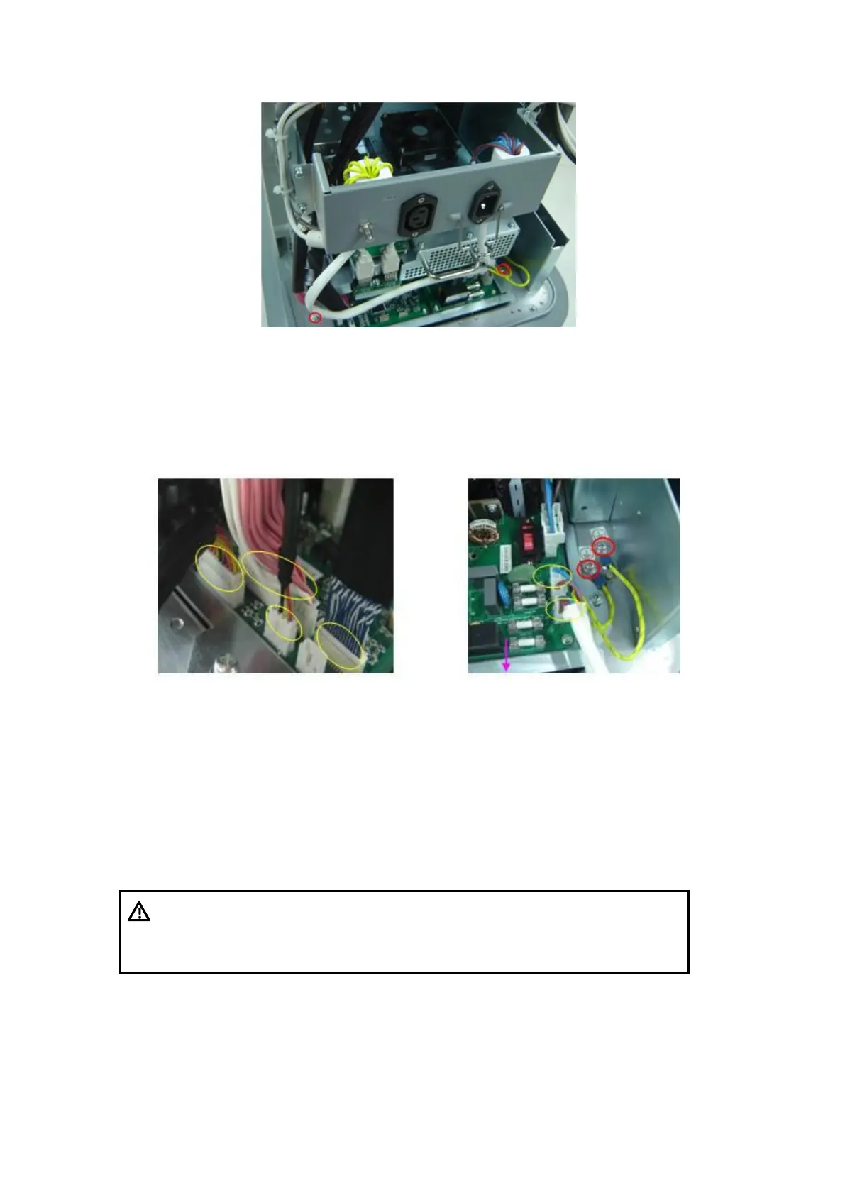
Fig 7-17 Disassemble the Power Module Assembly
3. Pull out the 4 cable plugs at the left side, and then pull out the 2 cable plugs at the
right side facing outwards, and then remove the screws M4X8 (2 pcs) for fixing
ground line terminal. Lift the module and pull outwards gently until you see another
cable plug, pull out the plug, then the power module can be removed.
Figure 7-18 Power module cables at the left side Figure 7-19 Power module cables
at the right side
7.4.6 Main Unit Box Module
Tool: cross-headed screwdriver. Please refer to Chapter 7.3.1 Tools Required for tools’
specifications.
1. Remove the IO module and main unit rear cover and remove the main unit fan
assembly (refer to chapter 7.4.2 IO Rear Board and 7.4.3 Machine Fan).
For machines that are configured with battery,
disconnect the battery connecting cable before
removing the main unit box module, otherwise,
machine may be damaged due to hot-plug.
2. Remove the power input assembly (refer to 7.4.4 Power Input Assembly chapter).
3. Remove or rotate rightwards and open the power input module: remove the M4X8
screws (3 pcs) of power input module, then the module can be rotated rightwards to
open, which facilitates disassembly and plugging of the main unit. Pull out the
 Loading...


