EasyManuals Logo
Home>Mindray>Medical Equipment>DC-30

Mindray DC-30 Service Manual

Mindray DC-30
213 pages
To Next Page IconTo Next Page
To Previous Page IconTo Previous Page
Page #16 background imageLoading...
Page #16 background image
1-4 Preface
1.2.3 General Symbols
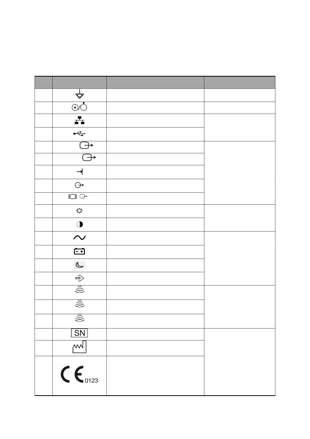
This system uses the symbols listed in the following table, and their meanings are explained as
well.
No.
Symbol
Description
Location
1
Equipotentiality
On the power supply panel
2
Power button
On the control panel
3
Network port
On the IO panel
4
USB ports
5
Video
Video output
On the IO panel
6
S-Video
S-Video output
7
Remote control port
8
Audio output
9
VGA signal output
10
Display brightness adjusting
On the right corner of the
display
11
Display contrast adjusting
12
AC Status Indicator
On the upper right corner
of the control panel
13
Battery Status Indicator
14
Standby indicator
15
Hard disk indicator
16
A
Probe port A
Below the probe port
17
B
Probe port B
18
C
Probe port C
19
Product serial number
Product label
20
Manufacture date
21
This product is provided with a CE
marking in accordance with the
regulations stated in Council Directive
93 / 42 / EEC concerning Medical
Devices. The number adjacent to the
CE marking (0123) is the number of the
EU-notified body certified for meeting
the requirements of the Directive.

Table of Contents

Questions and Answers:

Question and Answer IconNeed help?

Do you have a question about the Mindray DC-30 and is the answer not in the manual?

Mindray DC-30 Specifications

General IconGeneral
BrandMindray
ModelDC-30
CategoryMedical Equipment
LanguageEnglish

Related product manuals