Hardware Introduction
2-9
20
POUT77 POUT79 A+5 POUT73 POUT74
21
POUT65 POUT69 POUT75 A+5 POUT76
22
POUT67 POUT71 POUT72 POUT70 A+5
2.2.3.4. Interfaces to Peripherals
The connection board provides power supply for all peripherals, which includes the display,
hard disk, CD-ROM, keyboard and fans.
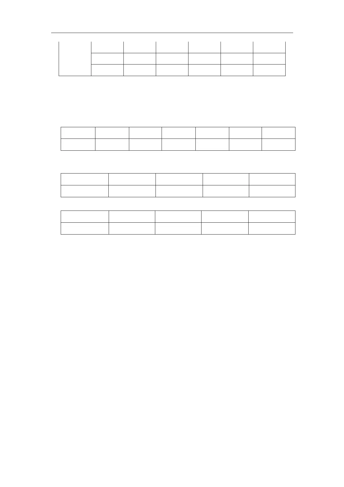
z J5, the interface between the connection board and display, is defined as the table below.
Pin 1 2 3 4 5 6
Signal 13.5v NC 13.5v GND NC GND
z J2, J3 and J4, the interfaces between the connection board and the hard disk, CD-ROM
and keyboard, is defined as the table below.
Pin 1 2 3 4
Signal GND GND 5v 12v
z J1, the interface between the connection board and fans, is defined as the table below.
Pin 1 2 3 4
Signal 12v 12v GND GND
2.2.4. Output Board
The output board, connected to the main board, provides signal path to peripherals and
download interface for the main board. It locates in the outmost part of the cabinet. It is
grounded well and accordance with the requirements of EMC and can filter differential mode
and common mode noise.
The diagram of the output board is shown as follows.

 Loading...


