Disassembly of DP-9900Plus/DP-9900
3-21
step 2 of 3.16).
2. Pull out the plugs from the OSD board of the LCD by the right side of the LCD
assembly, remove the M3X8 combination screws (10 pcs) securing the PCB
shielding cover, and then remove the PCB shielding cover.
3. Pull out the 2 plugs of the cable connecting the inverter board and the LCD, and
then pull out the plug of the cable connecting the inverter board and the control
board. Remove the M3X8 combination screws (2 pcs) securing the LCD inverter
board, and then remove the inverter board.
4. Pull out the plug of the cable connecting the inverter board and the control board,
and then pull out the plug of the cable connecting the control board and the LCD.
Remove the M3X8 combination screws (5 pcs) securing the LCD inverter board,
and then remove the control board.
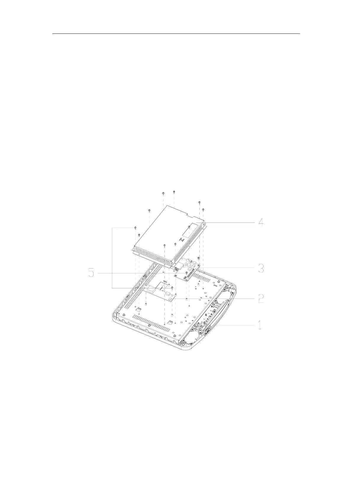
1. Front cover assembly of the LCD 2. Inverter board 3. Control board 4. PCB
shielding cover 5. M3X8 combination screws (17 pcs)
Disassembly of the inverter board and the control board
3.18. Replacing the LCD screen of the LCD Monitor
1. Remove the LCD assembly (refer to 3.15) and the rear cover of the LCD (refer to
step 2 of 3.16). Pull out the plugs from the OSD board.
2. Remove the M3X8 combination screws (11 pcs) securing the LCD assembly, and

 Loading...


