Hardware Introduction
2-21
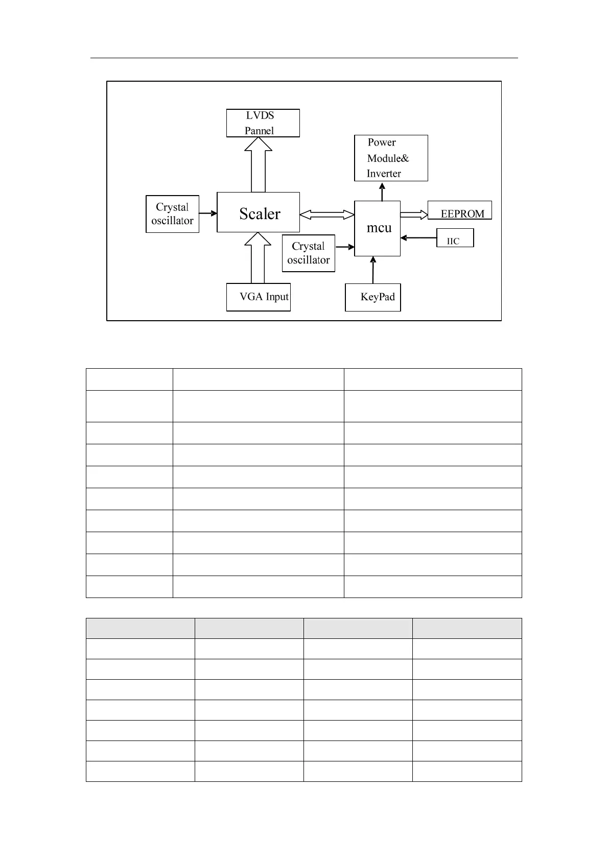
Functional Diagram of Regulating Board
The main ICs of different modules of the regulating board are shown below:
Pin Type Description
U1 LM2596-33
DC-DC conversion from 12V to
3.3V
U3 AMS1117 2.5 Conversion from 3.3V to 2.5V
U4 AIC1804-18PM Conversion from 3.3V to 1.8V
U5 24C16 EEPROM
U6 MTV412 MCU
U7 RTD2620 Signal processing
U8 K4D263238I GDDR
U9 4435 Panel Power On/Off
Y1/Y2 K24.000 Crystal Oscillator
Pin Definitions of LVDS Ports of the Regulating Board (J1)
Pin Definition Pin Definition
1
GND
2
GND
3
RXOIN3+
4
RXOIN3-
5
GND
6
RXOCKIN+
7
RXOCKIN-
8
GND
9
RXOIN2+
10
RXOIN2-
11
GND
12
RXOIN1+
13
RXOIN1-
14
GND

 Loading...


