 Loading...
Do you have a question about the Mindray Passport 12 and is the answer not in the manual?
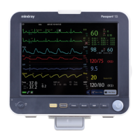
| SpO2 | Yes |
|---|---|
| NIBP | Yes |
| Respiration (RESP) | Yes |
| Temperature (TEMP) | Yes |
| IBP | Yes |
| Sidestream CO2 | Optional |
| Display | 12.1-inch color TFT |
| Display Type | TFT LCD touch screen |
| Battery Type | Lithium-ion battery |
| Connectivity | Wi-Fi, Ethernet |
| ECG | 3/5-lead |
| Recorder | Built-in thermal printer |
| Networking | Ethernet, optional Wi-Fi |
| Operating Temperature | 0 to 40 °C |
| Storage Temperature | -20 to 60 °C |
| Humidity Range | 15% to 95% (non-condensing) |
Provides crucial safety information, including warnings and cautions for proper operation.
Details critical warnings and cautions regarding electrical hazards, handling, and environmental factors.
Explains various symbols used on the equipment and in the manual for clear identification.
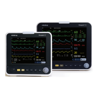
Overview of the patient monitor's design, functions, and basic operational principles.
Describes how the monitor connects to peripheral devices and installation support options.
Details the connectors on the rear of the monitor for peripheral device attachment.
Illustrates the main unit's internal architecture, including front and rear housing components.
Details components within the front housing: main board, keypad, alarm lamp, Wi-Fi module.
Details components within the rear housing: power boards, interface boards, recorder, etc.
Provides descriptions for AC/DC Power Board, Power Management Board, Interface Board, etc.
Details SpO2 Board, Parameter Connector Board, and Module Converter functions.
Describes Converter, IBP+C.O., CO2, and AG modules and their functions.
Instructions for opening packages, checking contents against the packing list, and handling damage.
Ensures site meets safety, environmental, and power requirements. Details environmental specifications.
Specifies electrical requirements, including line voltage, current, frequency, and grounding.
Details network standards, modulation, operating frequency, QoS, channel spacing, and baud rate.
Guides setting network type (LAN/WLAN) and configuring wireless network parameters like SSID and security.
Covers setting WLAN band/channels and managing security certificates for network access.
Configures Quality of Service (QoS) for network transactions and multicast parameters.
Lists supported hardware upgrades for functions like IBP, CO2, AG, Wi-Fi, and recorder.
Details methods for upgrading parameter modules, wireless function, and installing hooks.
Provides information and contact for performing software upgrades by authorized personnel.
Introduces testing procedures and preventative maintenance actions to ensure normal function.
Covers CO2 module leakage test, accuracy test, and calibration procedures.
Step-by-step guide for performing CO2 module calibration using gas cylinders.
Details AG module leakage test, accuracy test, and calibration procedures with standard gases.
Procedure for performing AG module calibration, including pressure and gas concentration checks.
Outlines recommended frequencies for performance tests and guidelines for visual inspection.
Covers ECG performance testing, verification, and respiration performance testing procedures.
Details SpO2 testing and NIBP leakage testing procedures, including required tools.
Step-by-step guide for performing NIBP accuracy tests using manometer and rigid vessel.
Covers temperature sensor testing and invasive blood pressure performance testing.
Details Cardiac Output (C.O.) testing and Nurse Call Reply performance testing procedures.
Covers electrical safety tests and the power-on self-test procedure for the monitor.
Procedures for touchscreen calibration and checking the recorder's functionality.
Details battery function/performance tests and network printer connectivity test.
Guides accessing factory maintenance, configuring central station, and checking software/monitor info.
Introduces troubleshooting steps and guidelines for replacing defective PCBs or parts.
Troubleshooting common power issues and display problems like blank screens or distorted images.
Addresses issues with alarm lamps, unresponsive buttons, or malfunctioning knobs.
Troubleshoots sound issues (alarms, keys) and battery charging or performance problems.
Covers recorder issues (no printout, poor quality) and output interface problems (analog, USB).
Troubleshoots data storage failures (SD card) and wired network connectivity issues.
Addresses common Wi-Fi issues such as disconnection, instability, and slow transmission.
Troubleshoots problems related to external parameter module connection and communication.
Lists required tools and essential preparation steps before disassembling the equipment.
Step-by-step guide to separating the main unit's front and rear halves.
Details disassembly of parameter modules, connector panels, and SpO2/Parameter boards.
Provides instructions for removing the pump, valve assembly, and the optional recorder.
Instructions for removing battery interface and power boards specifically for Passport 8.
Instructions for removing battery interface and power boards specifically for Passport 12.
Procedure for disconnecting and removing the power management board.
Instructions for removing the interface board for both Passport 8 and Passport 12.
Details removing the touchscreen control board and the Wi-Fi module.
Instructions for removing the SD card and the main control board.
Procedures for removing the touchscreen assembly and disassembling the screen.
Instructions for removing the keypad and the encoder assembly.
Details removing the external module interface board and the M03B module.
Instructions for removing the Sidestream and Microstream CO2 modules.
Procedure for removing the AG module.
Introduces the chapter on exploded views and parts lists for identifying and replacing components.
Provides exploded view and parts list for the Passport 8 Main Unit.
Details the exploded view and parts list for the Passport 8 Front Housing Subassembly.
Provides exploded view and parts list for the Passport 8 Rear Housing Assembly.
Details the exploded view and parts list for the Multi-parameter Assembly.
Provides exploded view and parts list for the Battery Compartment Assembly.
Details the exploded view and parts list for the NIBP Pump and Valve Kit.
Provides exploded view and parts list for the IBP_C.O. Module Assembly.
Details exploded view and parts list for IBP_C.O._Sidestream CO2 Module Assembly.
Provides exploded view and parts list for IBP_C.O._Microstream CO2 Module Assembly.
Provides exploded view and parts list for the Passport 12 Main Unit.
Details exploded view and parts list for the Passport 12 Front Housing Subassembly.
Provides exploded view and parts list for the Passport 12 Rear Housing Assembly.
Details exploded view and parts list for the Passport 12 Battery Compartment Assembly.
Provides exploded view and parts list for the IBP_C.O._AG Module Assembly.
Covers inspection of power cord plug, device enclosure, and accessories for safety compliance.
Checks device labelling and specifies tests required after equipment repair.
Details the form and limits for electrical safety inspection, including leakage and resistance tests.