24v
12v
Battery 1
Battery 1 Battery 2
Black
B-
Black B-
Red B+
Red B+
B+
B-
M+
M-
Control Board
Red
Red
Black
Black
Battery
Gauge
Motor
Steering
Housing
Black
White
White
Red M+
Red M+
Black M-
Black M-
Black
Advanced GPS
Navigation
Advanced
GPS Cable
Advanced
GPS Ethernet
Connector
Coil Cord
Accessory
Attachment
Black M-
Red M+
Control Head
Accessory
Attachment
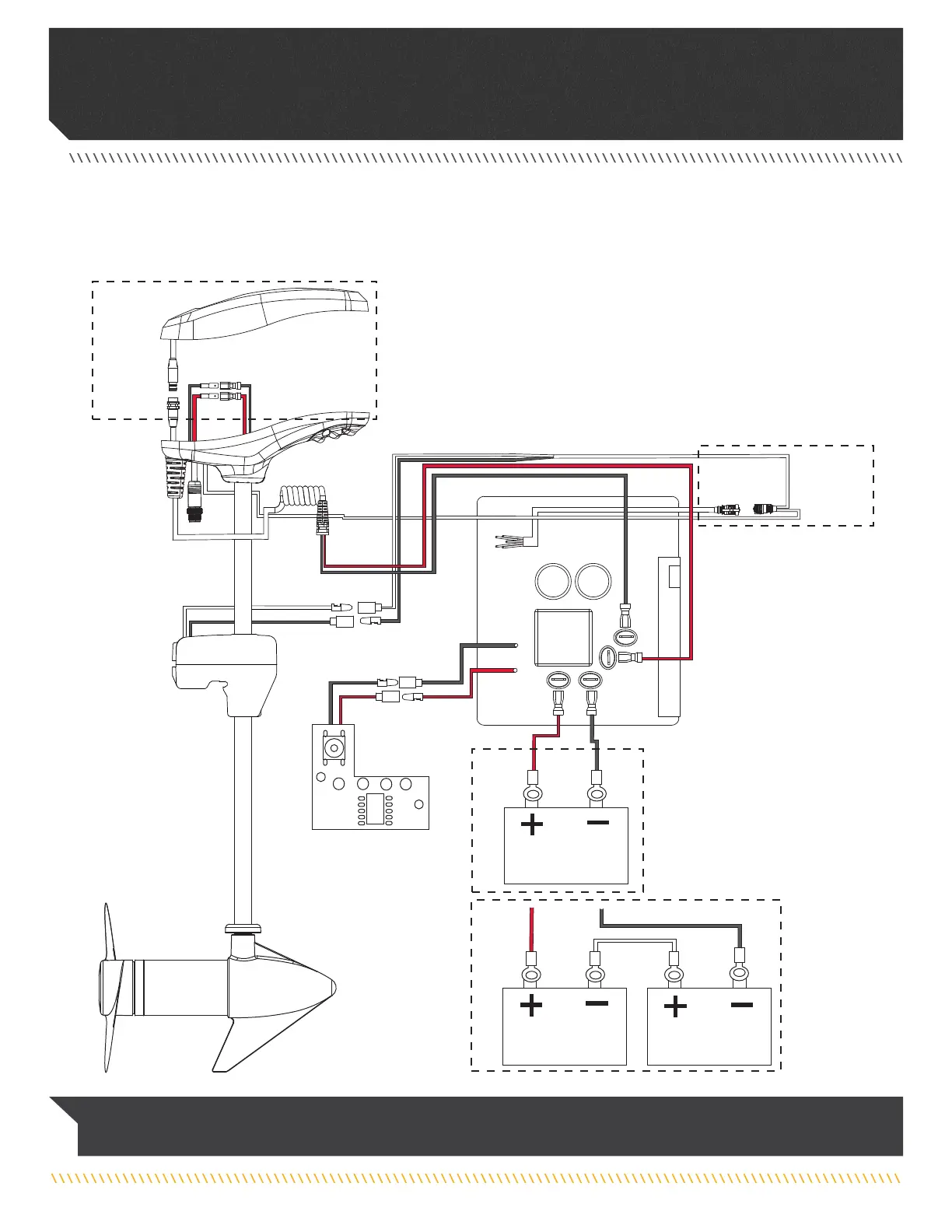
RIPTIDE POWERDRIVE WITH ADVANCED GPS NAVIGATION
The following Motor Wiring Diagram applies to all Riptide PowerDrive models that come factory installed with Advanced GPS Navigation.
NOTICE: This is a multi-voltage diagram. Double-check your motor's voltage for proper connections. Over-Current Protection
Devices are not shown in this illustration.
28 | minnkotamotors.com
©2023 Johnson Outdoors Marine Electronics, Inc.
MOTOR WIRING DIAGRAM
 Loading...