10
HWE1212A
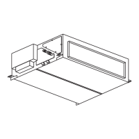
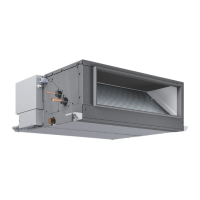
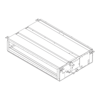
OUTLINES AND DIMENSIONS
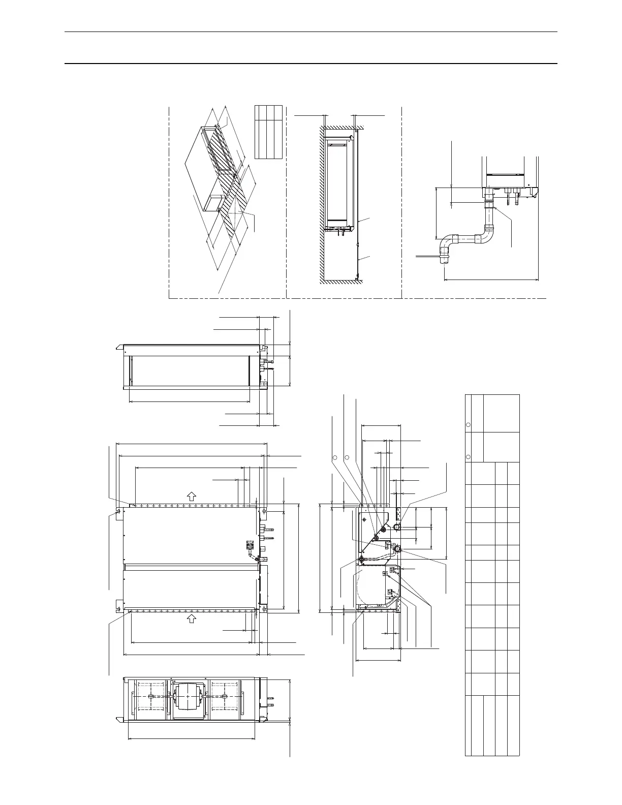
4. OUTLINES AND DIMENSIONS
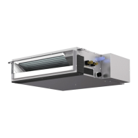
■ PEFY-P15·18·24·27·30·36·48·54NMHU-E2
Unit :mm(in.)
DE GHFACB
ø6.35ø12.7
ø9.52
ø15.88
1085
1250
PEFY-P27∙30NMHU-E2
PEFY-P36∙48∙54NMHU-E2
(31-1/2)
(42-3/4)
(49-1/4)
1039
1204
754
(29-11/16)
(40-15/16)
(47-7/16)
965
1130
680
(38)
(44-1/2)
885
1050
600
(23-5/8)
(34-7/8)
(41-3/8)
835
1000
550
(21-11/16)
(32-7/8)
(39-3/8)
42.5
25
50
(2)
(1-11/16)
(1)
17
21
11
800
1000
(19-11/16)
(31-1/2)
(39-3/8)
(1/4)
(3/8)
700
900
(17-3/4)
(27-9/16)
(35-7/16)
J
67
50
50
(2)
(2-11/16)
(2)
LK
(26-13/16)
800
15
19
10
500 450
(1/2)
(5/8)
PEFY-P24NMHU-E2
PEFY-P15∙18NMHU-E2
Note 1. Use an M10 screw for the suspension bolt (field supply).
2. Keep the service space for the maintenance from the bottom
when the heat exchanger is cleaned.
3. This drawing is for PEFY-P27∙30∙36∙48∙54NMHU-E2 models,
which have 2 fans.PEFY-P15∙18∙24NMHU-E2 models have 1 fan.
4. Make sure to install the air filter (field supply) on the air intake side.
In case field supplied air filter is used, attach it
where the filter service is easily done.
Air inlet Air outlet
Model
Gas pipe
1
Liquid pipe
2
2×5-ø3(1/8) holes
15(5/8)
L
50(2)
50x(J-1)=K (2x(J-1)=K)
23(15/16) B(Suspension bolt pitch)
A
60(2-3/8)
814(32-1/16)
904(35-5/8)
15(5/8)
29(1-3/16)
900(35-7/16)
24(1) 847(33-3/8)
10(7/16)
41
E(Duct)
94(3-3/4)250(9-7/8)
2×J-ø3(1/8) holes
143
58
25(1)
50x4=200
50(2)
326.5(12-7/8)
69 187
180 164.5
432(17-1/16)
50(2)
45(1-13/16)
50x5=250
380(15)
F
50(2)
40(1-5/8)
65(2-9/16)
C
50x(G-1)=H (2x(G-1)=H)
10(7/16)
16(11/16) 340(13-7/16)
D(Duct)
(Duct)
Suspension bolt hole
(Suspension bolt pitch)
80(3-3/16)
(2x4=7-7/8)
(2-3/4)
(7-1/8)
(6-1/2)
4-14×30(9/16x1-3/16) Slot2×G-ø3(1/8) holes
(7-3/8)
(Duct)
(2-5/16)
Terminal block
Terminal box
(Power source)
Control box
Drain pump
Drain pipe
brazing connection (gas)
Terminal block
(2x5=9-7/8)
Drain pipe
Drain pipe
(O.D.Ø32(1-1/4))
2×6-ø3(1/8) holes
brazing connection (liquid)
(O.D.ø32(1-1/4))
(5-11/16)
(1-5/8)
(Emergency drain)
(O.D.ø32(1-1/4))
(Gravity drain)
62(2-1/2)
115(4-9/16)
44.5(1-13/16)
115(4-9/16)
(Transmission)
Terminal block
29
34
(1-3/8)
(1-3/16)
700(27-9/16) Max
300(11-13/16) or less
(Actual length)
Drain hose
<Accessory>
(I.D.ø32(1-1/4))
0
-10
65 (2-9/16 )
-7/16
0
20(13/16) or more
20(13/16) or more
Access door Ceiling surface
Make the access door at the appointed position properly
for service maintenance.
Note2
50(2)
50(2)
M
625(24-5/8)
450(17-3/4)
100
~
200(3-15/16
~
7-7/8)
150
~200(5-15/16
~7-7/8)
700(27-9/16)
450(17-3/4)
Access door
1065
1230
PEFY-P27∙30NMHU-E2
PEFY-P36∙48∙54NMHU-E2
(30-3/4)
(4-15/16)
(48-7/16)
780
Model
Required space for service and maintenance.
M
PEFY-P15∙18∙24NMHU-E2
Refrigerant piping
1
Refrigerant piping
2
 Loading...