20
HWE1212A
DISASSEMBLY PROCEDURE-Fan
8-3. Fan
Procedures Explanatory figure
1. Remove the control box and its cover according to the
procedures detailed in section 8-2. Control box (page18).
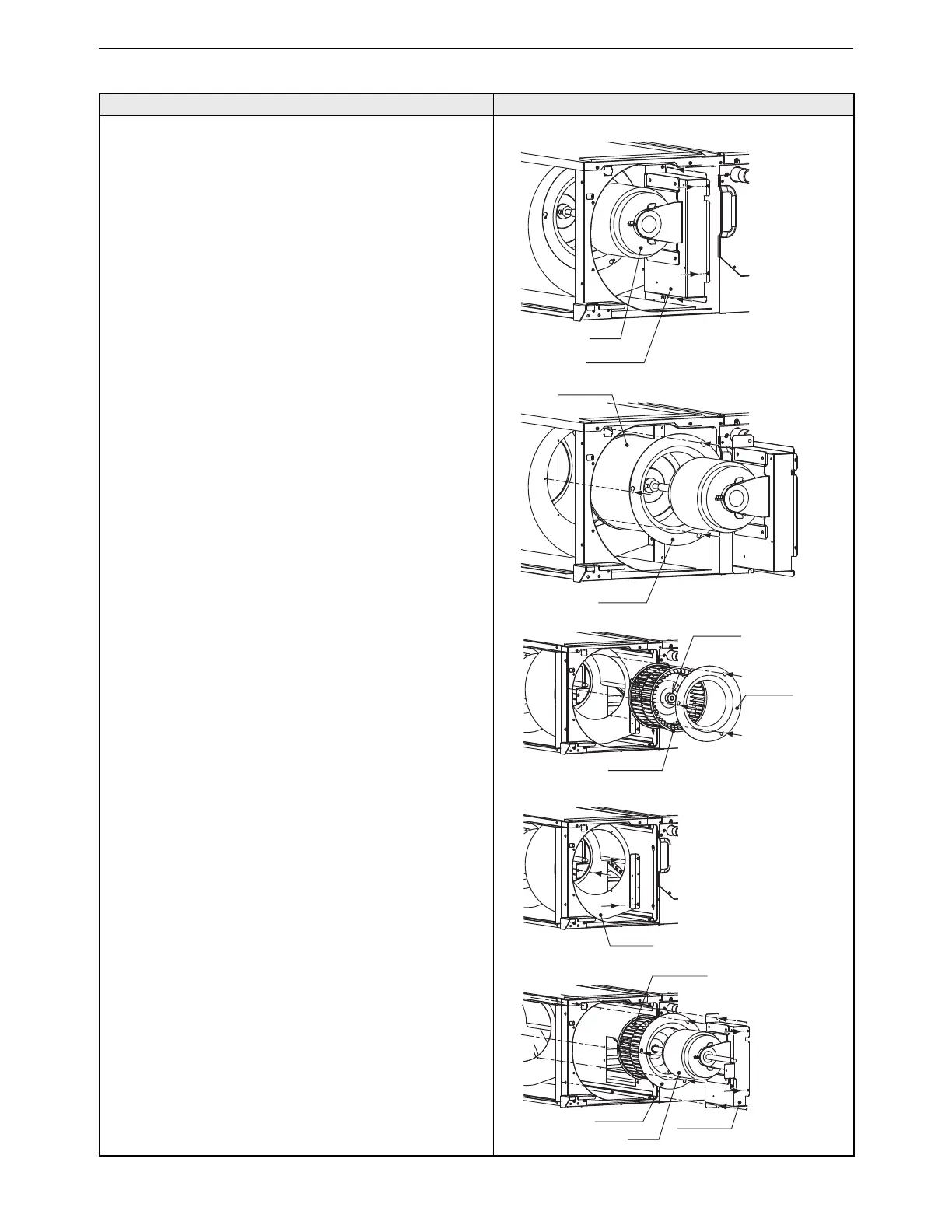
2. Removing the fan
P45-71 models (Figures 3-1 and 3-2)
(1) Remove the four motor base mounting screws.
(2) Loosen the three bellmouth mounting screws, and remove
the bellmouth.
(3) Pull out the fan along the guide rail.
*Use caution not to pinch the wiring.
*Motor is heavy. Use caution to avoid injuries.
P80-160 models (Figures 3-3, 3-4, and 3-5)
(1) Loosen the three front bellmouth mounting screws, and
remove the bellmouth.
(2) Loosen the sirocco fan set screws, and remove the
sirocco fan.
(3) Remove the three front fan case mounting screws.
(4) Remove the four motor base mounting screws.
(5) Loosen the three back bellmouth, and remove the
bellmouth.
(6) Pull out the fan along the guide rail.
*Use caution not to pinch the wiring.
*Motor is heavy. Use caution to avoid injuries.
Motor base
Motor
Bellmouth
Sirocco fan
Figure 3-1
Figure 3-2
Sirocco fan
Bellmouth
Motor base
Motor
Fan case
Bellmouth
Set screw
Figure 3-3
Figure 3-4
Figure 3-5
Sirocco fan
 Loading...