21
HWE1212A
DISASSEMBLY PROCEDURE-LEV•Pipe thermistor
8-4. LEV•Pipe thermistor
Procedures Explanatory figure
1. Remove the service panel according to the procedures
detailed in section 8-1. Service panel (page17).
2. Remove the control box cover according to the
procedures detailed in section 8-2. Control box
(page18).
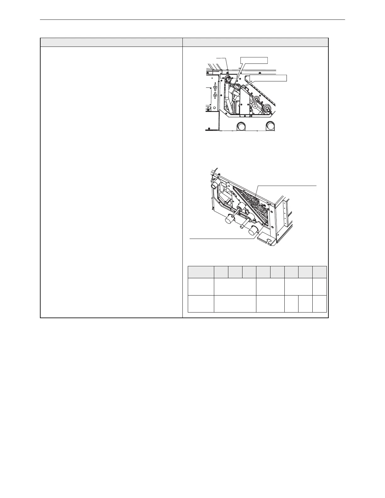
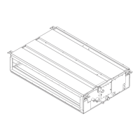
3. Removing the LEV (Figure 4-1)
(1) Disconnect connector CN60 from the control board.
(2) Remove the drive motor using two spanners.
(3) To remove the valving element, first take the
first four steps in section 8-7. Heat exchanger
(page24) to remove the plastic cover. Be sure to
protect the surrounding parts, such as insulation
and wiring, from flame.
4. Removing the pipe thermistor (Figure 4-2)
(1) Disconnect connectors CN21 and CN29 from the
control board.
(2) Take the pipe thermistor out of the holder.
Liquid pipe temperature thermistor
Gas pipe temperature thermistor
LEV
Figure 4-1
Figure 4-2
Drive motor
Valving element
Thermistor position list
P45
model
P50
model
P71
model
P80
model
P90
model
P112
model
P140
model
P160
model
Liquid pipe
temperature
thermistor
4th path 7th path 8th path
5th
path
Gas pipe
temperature
thermistor
3rd path 4.5th path
3rd
path
7th
path
4th
path