22
HWE1212A
DISASSEMBLY PROCEDURE-Drain pump•Drain sensor
8-5. Drain pump•Drain sensor
Procedures Explanatory figure
1. Remove the service panels
2
and
3
according to
the procedures detailed in section 8-1. Service panel
(page17).
2. Remove the control box cover according to the
procedures detailed in section 8-2. Control box
(page18).
3. Disconnect the drain pump relay connector (CN31:
white) from the control board.
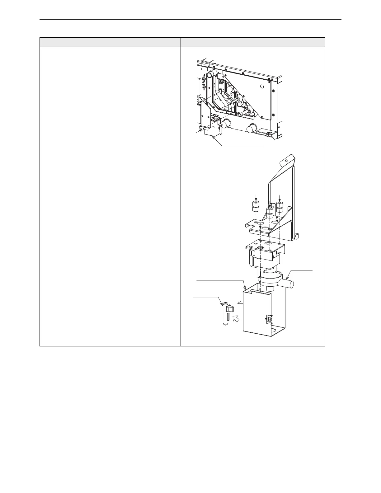
4. Removing the drain pump assembly (Figure 5-1)
(1) Remove the two drain pump mounting screws.
5. Removing the drain pump and drain sensor (Figure
5-2)
(1) Remove the two drain pump cover sheet metal
mounting screws.
(2) Remove the three drain pump mounting screws.
(3) Pull the drain sensor out of the drain pump cover
sheet metal.
Drain pump assembly
Figure 5-1
Figure 5-2
Pump cover sheet metal
Drain sensor
Drain pump
 Loading...