19
HWE1212A
DISASSEMBLY PROCEDURE-Control box
Procedures Explanatory figure
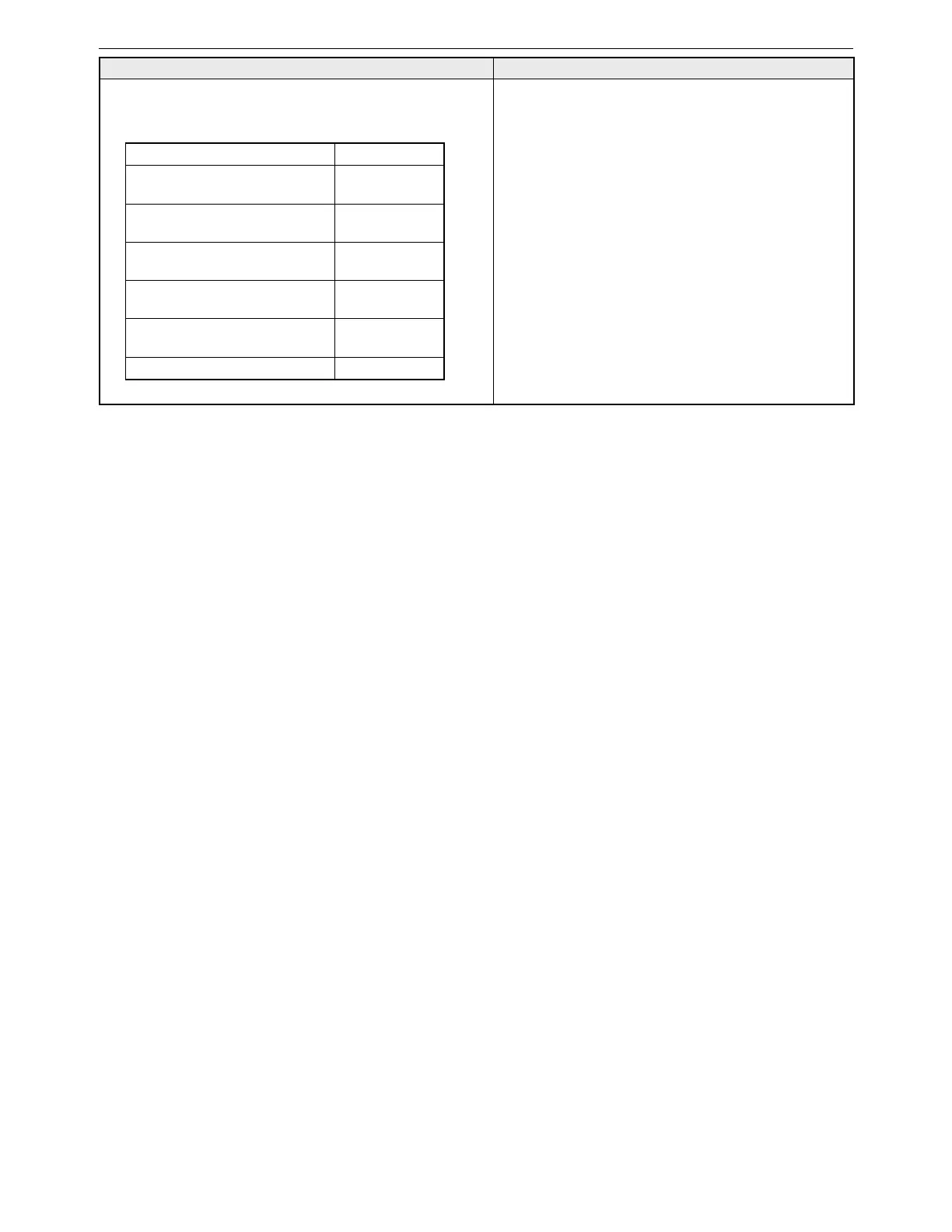
2. Removing the control box (Figure 2-2)
(1) Disconnect the wiring from the control board and the relay
connectors.
LEV1 wiring CN60•6P•White
Fan motor wiring
Relay connector•
9P•White
Indoor temperature thermistor
wiring
CN20•2P•Red
Liquid pipe temperature thermistor
wiring
CN21•2P•White
Gas pipe temperature thermistor
wiring
CN29•2P•Black
Drain pump wiring
Relay connector•
3P•White
Drain sensor wiring CN31•3P•White
(2) Remove the two control box mounting screws.
 Loading...