WALL-MOUNTED Outdoot UnitM series
WIRING DIAGRAM
WALL-
MOUNTED
C-31
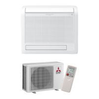
C.1.3.2 Outdoor Unit
MU-GA20VB
MU-GA25VB
OUTDOOR UNIT
OUTDOOR UNIT
C2
C1
WHT
POWER SUPPLY
~/N 230V 50Hz
CIRCUIT
BREAKER
BLU
BRN
WHT
RED
BLU
WHT
BLK
RED
12V
TO INDOOR
UNIT
CONNECTING
WHT
BLK
DSAR
52C
TB2
2
1
C
R
S
GRN/YLW
PE
N
L
BRN
TB1
COM
52C
NO
MC
1
3
2
BLK
RED
WHT
MF
NOTE: 1. About the indoor side electric wiring refer to the indoor unit electric wiring diagram for servicing.
2. Use copper conductors only. (For field wiring)
3. Symbols below indicate.
: Terminal block, : Connector
SYMBOL
TB2
52C
SYMBOL
MC
MF
TB1
SYMBOL
C1
C2
DSAR
NAME
NAME NAME
COMPRESSOR CAPACITOR
OUTDOOR FAN CAPACITOR
SURGE ABSORBER
COMPRESSOR(INNER PROTECTOR)
TERMINAL BLOCK
COMPRESSOR CONTACTOR
OUTDOOR FAN MOTOR(INNER FUSE)
TERMINAL BLOCK
 Loading...