7
5
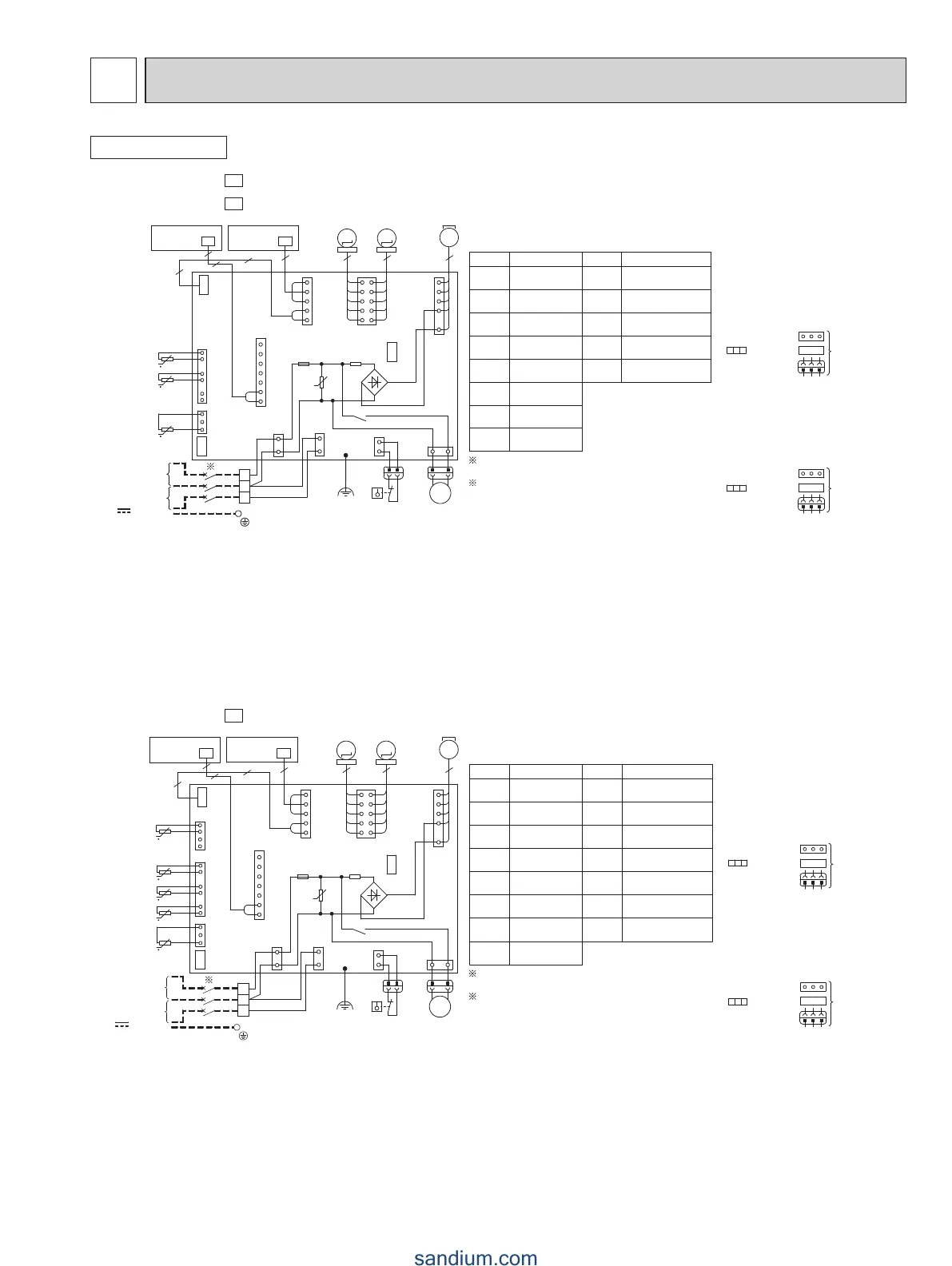
WIRING DIAGRAM
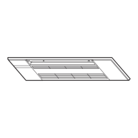
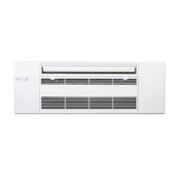
INDOOR UNIT
MLZ-KP09NA-
U1
MLZ-KP12NA-
U1
M M
M
1~
FROM OUTDOOR UNIT
CONNECTING WIRES
(POWER SUPPLY)
208/230V AC 60Hz
TO OUTDOOR UNIT
CONNECTING WIRES
S3
S2
S1
CN125
1
5
DISP
P.C.BOARD
CN302
CN106
6
NR11
3
1
CN202
3 5 5
6
1
MF
MS
3~
5
1
1
21
9
10
MV1
MV2
CN301
DP
CN145
CN201
LD103
6
CN112
1
CN111
1
3
1
3
F11
U
CN211
CN151
RT13
RT12
RT11
TB
2
1
CN1N1
1 3
X11
BK
BU
BU
RD
INDOOR ELECTRONIC
CONTROL P.C. BOARD
BK
REC
P.C.BOARD
R111
1
1
3
3
2
2
7
1
CN1M1
2
2
2
CN24
CN105
~
-
~
+
TO OUTDOOR UNIT
CONNECTING WIRES
12-24V
RESISTOR
COIL TEMP.
THERMISTOR(MAIN)
COIL TEMP.
THERMISTOR(SUB)
VARISTOR
RT13
RT12
NR11
FUSE
(T3.15AL250V)
DRAIN PUMP
FLOAT SENSOR
FS
DP
HORIZONTAL
VANE MOTOR
VERTICAL
VANE MOTOR
TERMINAL
BLOCK
MV1
MV2
F11
TB
RELAYX11
ROOM TEMP.
THERMISTOR
SYMBOL SYMBOL
MF FAN MOTOR
RT11
R111
NAME
NAME
t
t
t
FS
A disconnect should be
required by local code.
Se procurer un
sectionneur conforme aux
réglementations locales.
NOTES :
1.About the outdoor side electric wiring
refer to the outdoor unit electric wiring
diagram for servicing.
2.Use copper conductors only.
(For field wiring)
3.Symbols below indicate.
: Terminal
block
: Connector
: Borne
: Connecteur
REMARQUES :
1.Pour le câblage électronique côté
extérieur, se reporter au schéma
d'entretien du câblage électronique
de l'appareil extérieur.
2.Utiliser des fils d'alimentation en cuivre.
3.Les symboles ont les significations
suivantes
MLZ-KP18NA-
U1
M M
t
t
t
t
t
M
1~
~
-
~
+
S3
S2
S1
CN125
1
5
DISP
P.C.BOARD
CN302
6
NR11
3
1
CN202
3 5 5
6
1
MF
MS
3~
5
1
1
21
9
10
MV1
MV2
CN301
DP
CN145
CN201
LD103
6
CN112
1
CN111
1
3
1
3
F11
U
CN211
CN151
RT13
RT14
RT12
RT11
TB
2
1
CN1N1
1 3
X11
BU
BU
RD
INDOOR ELECTRONIC
CONTROL P.C. BOARD
BK
REC
P.C.BOARD
R111
1
1
3
3
2
2
7
1
CN1M1
2
2
2
CN24
CN105
RT15
1
CN113
4
BK
CN106
RESISTOR
COIL TEMP.
THERMISTOR(MAIN1)
COIL TEMP.
THERMISTOR(MAIN2)
COIL TEMP.
THERMISTOR(MAIN3)
COIL TEMP.
THERMISTOR(SUB)
VARISTOR
RT13
RT12
RT15
RT14
NR11
FUSE
(T3.15AL250V)
DRAIN PUMP
FLOAT SENSOR
FS
DP
HORIZONTAL
VANE MOTOR
VERTICAL
VANE MOTOR
TERMINAL
BLOCK
MV1
MV2
F11
TB
RELAYX11
ROOM TEMP.
THERMISTOR
SYMBOL SYMBOL
MF FAN MOTOR
RT11
R111
NAME
NAME
A disconnect should be
required by local code.
Se procurer un
sectionneur conforme aux
réglementations locales.
REMARQUES :
1.Pour le câblage électronique côté
extérieur, se reporter au schéma
d'entretien du câblage électronique
de l'appareil extérieur.
2.Utiliser des fils d'alimentation en cuivre.
3.Les symboles ont les significations
suivantes
NOTES :
1.About the outdoor side electric wiring
refer to the outdoor unit electric wiring
diagram for servicing.
2.Use copper conductors only.
(For field wiring)
3.Symbols below indicate.
FROM OUTDOOR UNIT
CONNECTING WIRES
(POWER SUPPLY)
208/230V AC 60Hz
TO OUTDOOR UNIT
CONNECTING WIRES
TO OUTDOOR UNIT
CONNECTING WIRES
12-24V
: Terminal
block
: Connector
: Borne
: Connecteur
FS
 Loading...