21
4 When connecting multiple units
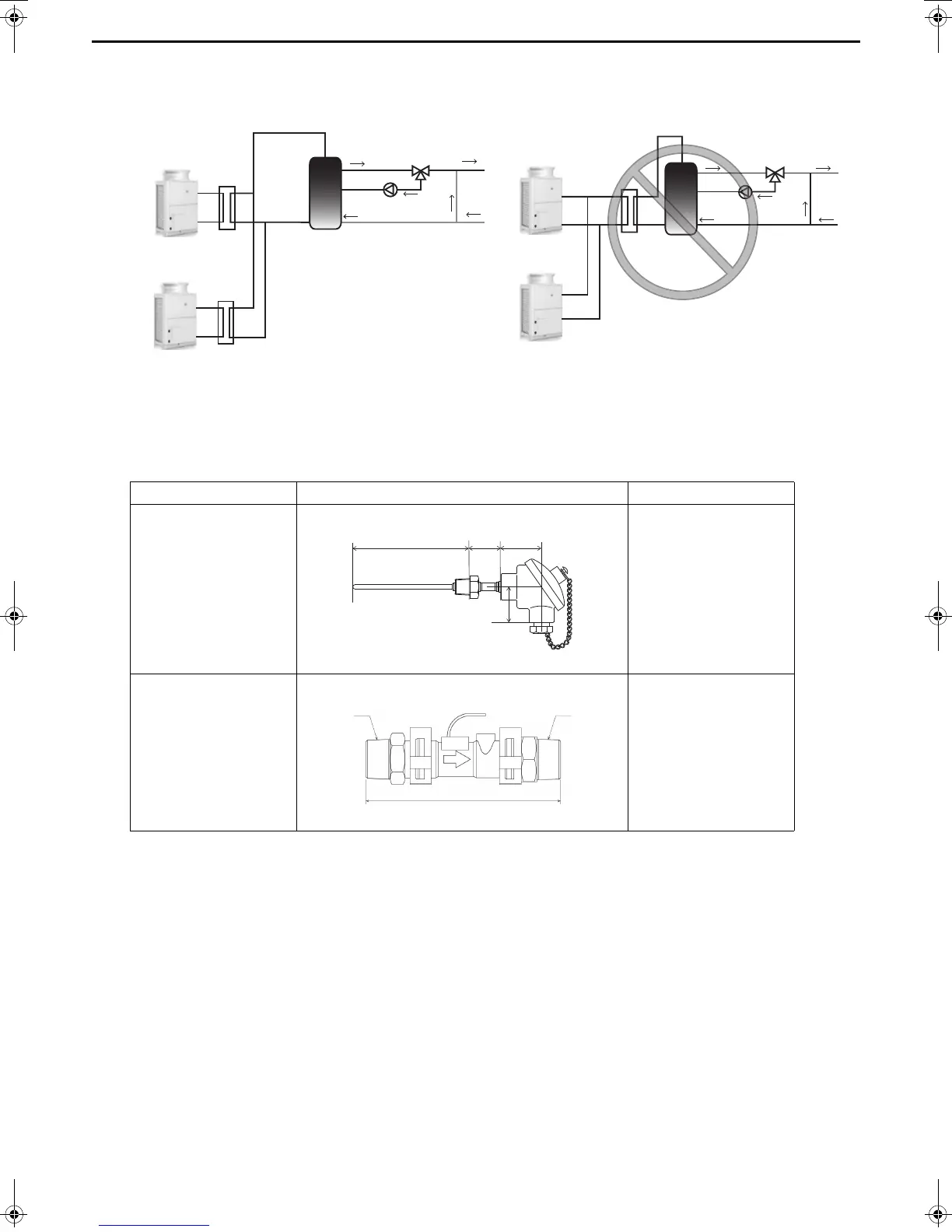
To connect multiple units, configure one secondary side circuit system for each unit as shown in the figure
below. (Install a heat exchanger, flow sensor, and thermistor for each unit.)
(3) Optional parts
The flow sensor and thermistor in the system are sold separately.
For the pipe connection method, refer to the manuals of the optional parts (Q-1SCK).
(4) Setting method for secondary side control
After configuring the secondary side control system, perform the following operation to perform the secondary side
control operation.
1. Set the digital setting item "121" to 1 (for details on the operating procedure, refer to page 28).
2. Perform a water flow rate adjustment operation (for details, refer to “Water flow rate adjustment operation (when
the secondary side control is enabled)” (page 37)).
Secondary circuit kit Q-1SCK The size and length noted are approximate.
Parts Shape Specification
Thermistor
A: 157 mm
B: 42 mm
C: 54 mm
D: 48 mm
Flow sensor
A: 129 mm
B: R3/4
C: R3/4
Wiring length: 1.9 m
QAHV-
N560YA-HPB
QAHV-
N560YA-HPB
QAHV-
N560YA-HPB
QAHV-
N560YA-HPB
Storage tank
Storage tank
WT08219X05.book 21 ページ 2018年10月1日 月曜日 午後7時47分
 Loading...