51
5. Electrical Wiring Installation
[1] Main Power Supply Wiring and Switch Capacity
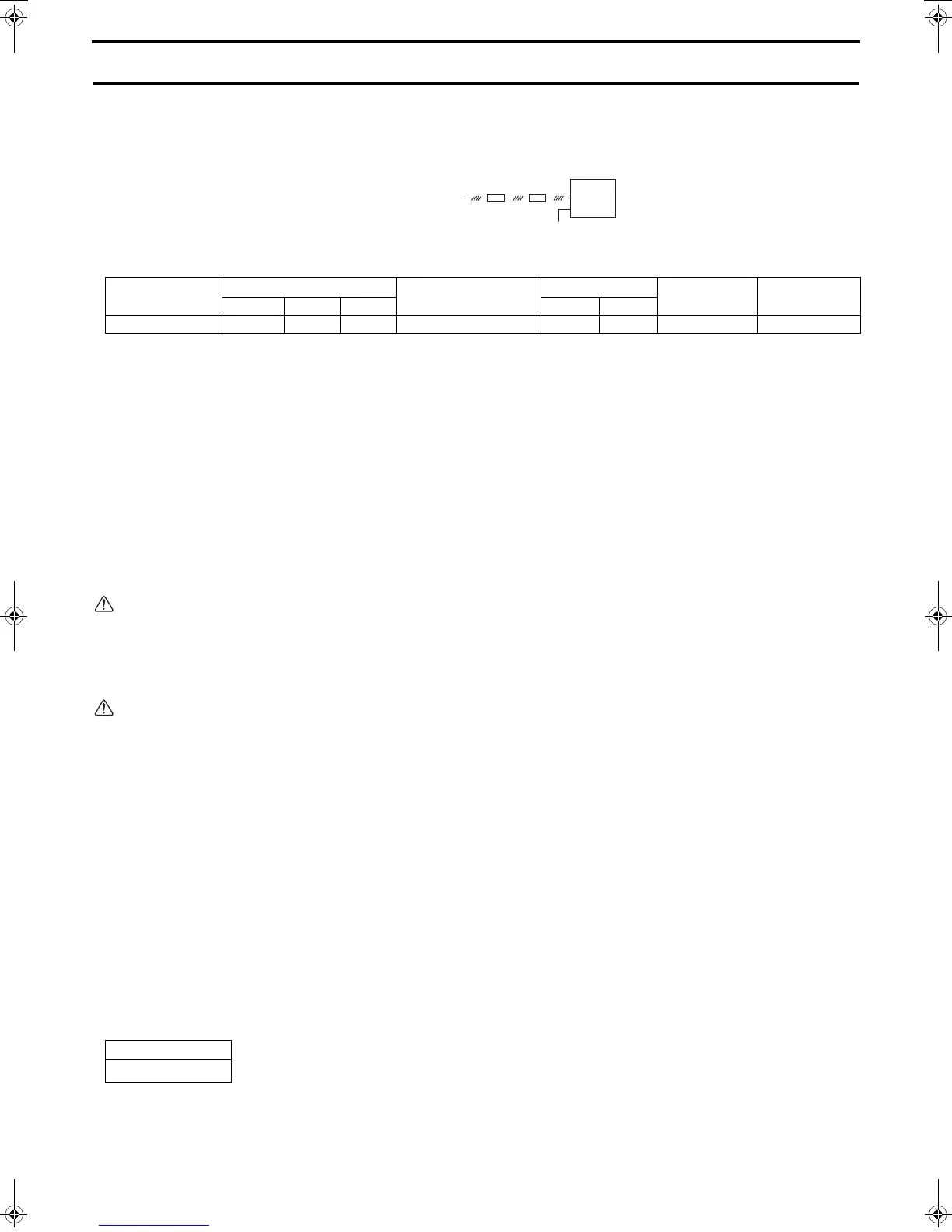
Schematic Drawing of Wiring (Example)
Main power supply wire size, switch capacities, and system impedance
1. Use a dedicated power supply for each unit. Ensure that each unit is wired individually.
2. When installing wiring, consider ambient conditions (e.g., temperature, sunlight, rain).
3. The wire size is the minimum value for metal conduit wiring. If voltage drop is a problem, use a wire that is
one size thicker.
Make sure the power-supply voltage does not drop more than 10%.
4. Specific wiring requirements should adhere to the wiring regulations of the region.
5. Power supply cords of appliances for outdoor use shall not be lighter than polychloroprene sheathed
flexible cord (design 60245 IEC57).
6. A switch with at least 3 mm contact separation in each pole shall be provided by the Air Conditioner
installer.
7. Do not install a phase advancing capacitor on the motor. Doing so may damage the capacitor and result in
fire.
Warning:
• Be sure to use specified wires and ensure no external force is imparted to terminal connections. Loose
connections may cause overheating and fire.
• Be sure to use the appropriate type of overcurrent protection switch. Note that overcurrent may include
direct current.
Caution:
• Some installation sites may require an installation of an earth leakage breaker for the inverter. If no earth
leakage breaker is installed, there is a danger of electric shock.
• Only use properly rated breakers and fuses. Using a fuse or wire of the wrong capacity may cause
malfunction or fire.
Note:
• This device is intended for the connection to a power supply system with a maximum permissible system
impedance shown in the above table at the interface point (power service box) of the user’s supply.
• Ensure that this device is connected only to a power supply system that fulfills the requirements above.
If necessary, consult the public power supply company for the system impedance at the interface point.
• This equipment complies with IEC 61000-3-12 provided that the short-circuit power S
SC
is greater than or
equal to S
SC
(*2) at the interface point between the user’s supply and the public system. It is the
responsibility of the installer or user of the equipment to ensure, in consultation with the distribution
network operator if necessary, that the equipment is connected only to a supply with a short-circuit power
S
SC
greater than or equal to S
SC
(*2).
S
SC
(*2)
A: Switch (with current breaking
capability)
B: Current leakage breaker
C: Outdoor unit
Model
Minimum wire thickness (mm
2
)
Current leakage breaker
Local swtich (A)
No-fuse breaker (A)
Max. Permissive
System Impedance
Main cable Branch Ground Capacity Fuse
QAHV-N560YA-HPB 10 - 10 63 A 100 mA 0.1 sec. or less 63 63 63 0.21
S
SC
(MVA)
2.62
B
C
3N~380–415V
L
1, L2, L3, N
A
PE
WT08219X05.book 51 ページ 2018年10月1日 月曜日 午後7時47分
 Loading...