Caution
Ⓐ
Ⓑ
[Figure 1]
[Figure 2]
Hook
Screw
30
30
Ⓐ Ⓑ
PANEL INSTALLATION MANUAL
Please read this manual together with the indoor unit’s installation manual.
WARNING
Fasten the wiring to the terminal securely and hold the cable securely so as not
to apply unexpected stress on the terminal.
Loose connection or hold will cause abnormal heat generation or fire.
Make sure the power supply is turned off when electric wiring work.
Otherwise, electric shock, malfunction and improper running may occur.
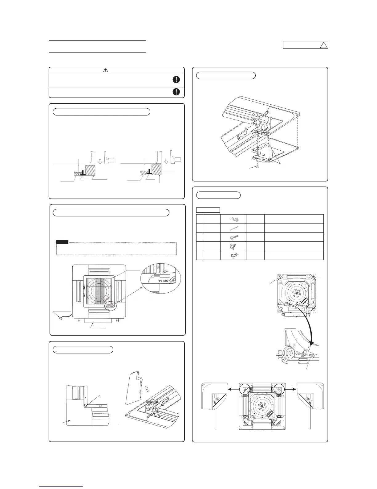
①Checking the indoor unit installation position
• Read this manual together with the air conditioner installation manual carefully.
• Check if the gap between the ceiling plane and the indoor unit is correct by inserting the
level gauge into the air outlet port of the indoor unit. (See below drawing)
• Adjust the installation elevation if necessary.
• Remove the level gauge before you attach the panel.
• Unscrew the screw from the corner area, pull the corner panel toward the direction
indicated by the arrow mark.
• First insert the part “a” of a corner panel into the part “A” of the cover panel, engage two
hooks and tighten the screw.
1. Take note that there is an orientation to install the panel.
• Attach the panel with the orientation shown on the below.
• Align the “PIPE SIDE” mark (on the panel) with the refrigerant pipes on the indoor unit.
2. The intake grille can also be attached in a rotated position by 90 degrees.
1. Screw in two bolts out of the four supplied with
the panel by about slightly less than 5mm.
( mark ⒶⒷ) [Figure 1]
2. Attach the hook supplied with the panel to the
main body with the hook fixing screw (1 screw).
[Figure 2]
3. Open the intake grille.
4. Please remove the screw of a corner panel and
remove a corner panel. (four places)
5. A panel is hooked on two bolts ( mark ⒶⒷ).
[Figure 3]
· In case the orientation of the panel is not correct, it will lead to air leakage and also
it is not possible to connect the louver motor wiring.
②Orientation of the panel and return air grille installation
③Removing a corner panel
④Attaching a corner panel
⑤Panel installation
Accessories
Use level gauges
as reference, adjust
the bottom to the
face of the indoor
unit.
Use level gauges
as reference, adjust
the bottom to the
face of the indoor
unit.
When the ceiling panel comes below
the T bar, align the bottom of the level
gauge to the lower face of the ceiling
panel.
Diffuser
Ceiling panel
Ceiling panel
Intake grille
Refrigerant
pipes side
Control box
Drain pipe side
Screw
Screw
Hook
Corner
panel
T-bar
T-bar
Level gauge
(insulation)
Level gauge
(insulation)
Diffuser
Louver motor
connector
• Install the panel on the unit after completing the electrical wiring.
1
2
3
4
5
Hook
Chain
Screw
Screw
Screw
1 piece
2 pieces
4 pieces
1 piece
2 pieces
For fixing temporarily
For hoisting the panel
For attaching a hook
For attaching a chain
[Figure 3]
 Loading...