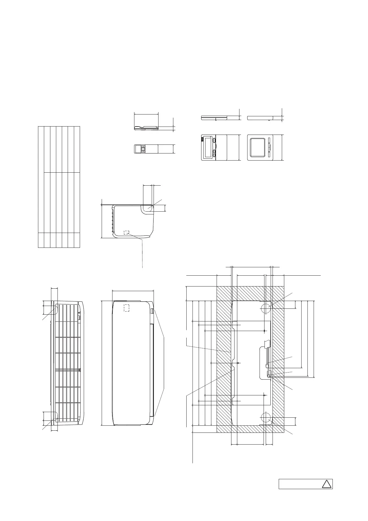
Wireless remote control
Wired remote control
(Option)
Space for installation and service when viewing from the front
Unit:mm
Notes(1)The model name label is attached
on the right side of the unit.
(2)To connect the wired remote control,
the interface kit(SC-BIKN2-E)is required.
□120
19
60 24
167
45
45
870
290
Outlet for downward piping
(Refer to the top view)
230 3
31 06
530
450
185
190
43
170
585
13
(Service space)
Unit
(Service space)
(Service space)
Installation board
142.5 142.5
100
50
9
47
268
47
80 100
Terminal block
60 3535 60
□120 19
210
55 55
537
528
469
(Service space)
170
210
435 435
45
F
D E
A
B
C
F F
Symbol
Gas piping
A
Content
φ9.52(3/8")(Flare)
Hole on wall for right rear piping
Hole on wall for left rear piping
Outlet for piping(on both side)
Drain hose
F
E
C
D
(φ65)
VP16
(φ65)
φ6.35(1/4")(Flare)
Liquid piping
B
B
RLF000Z103
2. EXTERIOR DIMENSIONS
(1)
Indoor units
(a)
Wall mounted type (SRK)
Models SRK20ZS-W, 25ZS-W, 35ZS-W
SRK20ZS-WB, 25ZS-WB, 35ZS-WB
SRK20ZS-WT, 25ZS-WT, 35ZS-WT
-
19
-
'21 • SRK-T-299
 Loading...