Model name
Power cable, indoor-outdoor connecting wires
Switchgear or circuit breaker capacity should be chosen according to national or regional electricity
The power cable specifications are based on the assumption that a metal or plastic conduit is used
with no more than three cables contained in a conduit and a voltage drop is 2
%. For an installation
falling outside of these conditions, please follow the national or regional electricity regulations.
2.0mm
×
3 22 1.5mm
×
4
SRC20ZS-WA
SRC25ZS-WA2
SRC35ZS-WA2
9
The wire numbers include Earth wire
(Yellow/Green)
*
2 2
2
N
regulations.
The specifications shown in the above table are for units without heaters. For units with heaters, refer
to the installation instructions or the construction instructions of the indoor unit.
MAX running current Power cable
wire size
×
number*(A)
Power cable length
(m)
Connecting cable
wire size
×
number*
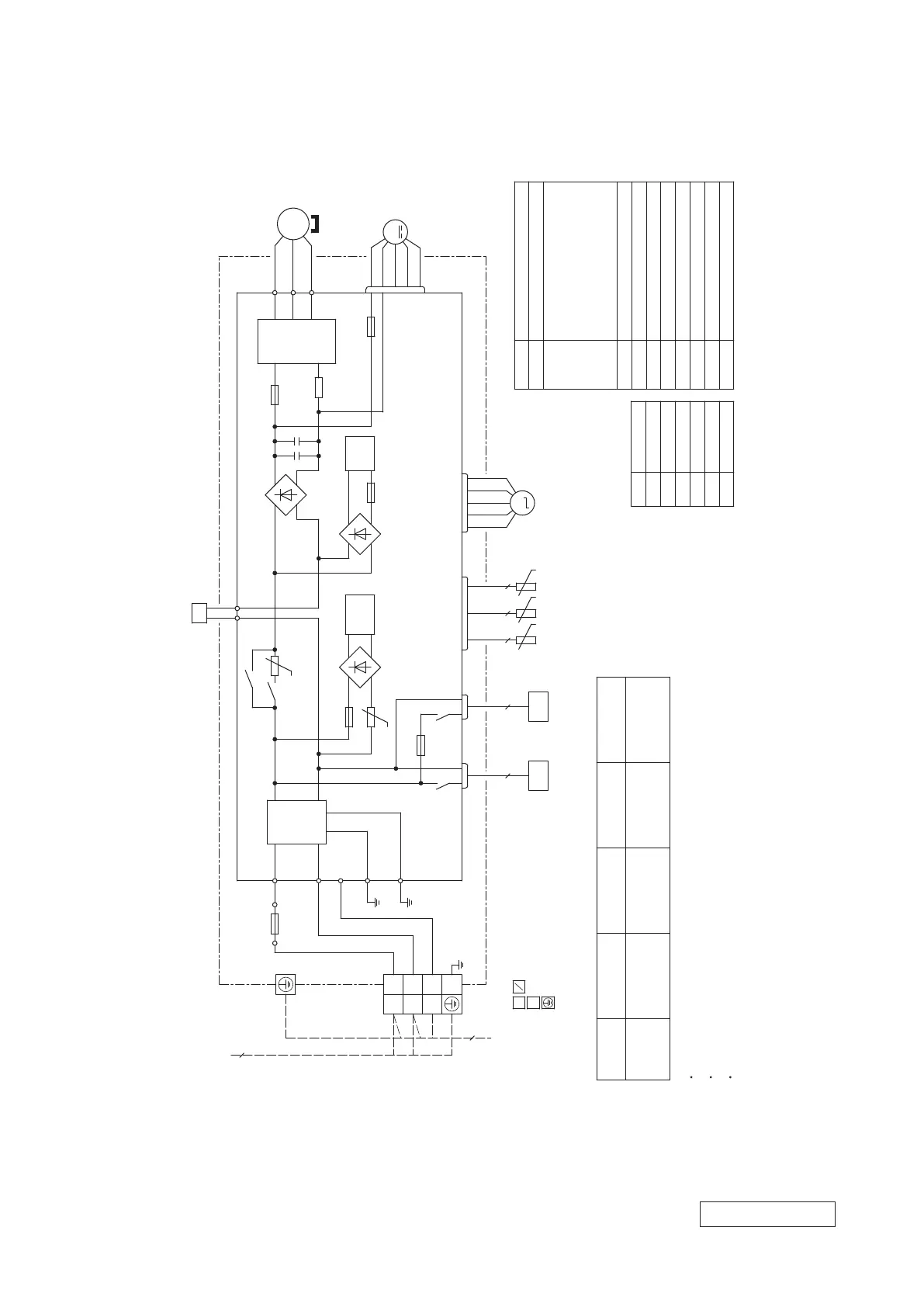
TH4 Discharge pipe temperature sensor
TH3 Outdoor air temperature sensor
TH2 Heat exchanger temperature sensor
L Reactor
FMo Fan motor
EEV Electric expansion valve(coil)
CM Compressor motor
CNTH
CNFAN
CNEEV
CN20S Connector
20S 4-way valve(coil)
Item Description
BK Black
Mark Color
RD Red
WH White
OR Orange
YE Yellow
YG
Yellow/Green
(BK)
(WH)
(RD)
V
W
U
PCB ASSY PCB1
M
MS
TRANSISTOR
POWER
POWER
T 1A L 250V
W
V
UP
N
CNTH CNEEV
CNFAN
3〜
+
S.IN
R.IN
G1
250V 15A
F7
C-2
(RD)
CN20S
(WH)
(WH)
F 3.15A L 250V
F1
(BK)
(BK)
(WH)
(YG)
(YG)
(RD)
G2
20S
〜
〜
+
−
SWITCHING
CIRCUIT
+
F3
FILTER
NOISE
L 1
N 2
3
(YG)
EEV
L
FMo
CM
TH4TH2 TH3
2 2
4
22
(BK)
3
T
SIGNAL WIRE
EARTH WIRE
M
1
3
250V 20A
F2
(YE) (OR)
T1 T2
〜
〜
+
−
〜
〜
+
−
CIRCUIT
PAM
250V 10A
F4
t゜
t゜
t゜
t゜
t゜
TB1
BLOCK
TERMINAL
H
2
CNHEAT
T 1A L 250V
F6
H Heater
CNHEAT
STACK4
DIODE
STACK2
DIODE
STACK1
DIODE
Color marks
Meaning of marks
1 Phase
220V 60Hz
RWC000Z307
(2)
Outdoor units
Models SRC20ZS-WA, 25ZS-WA2, 35ZS-WA2
-
31
-
'21 • SRK-T-299
 Loading...