'21 • SRK-T-299
-
98
-
-
22
-
’20・SRF-DB-310D・
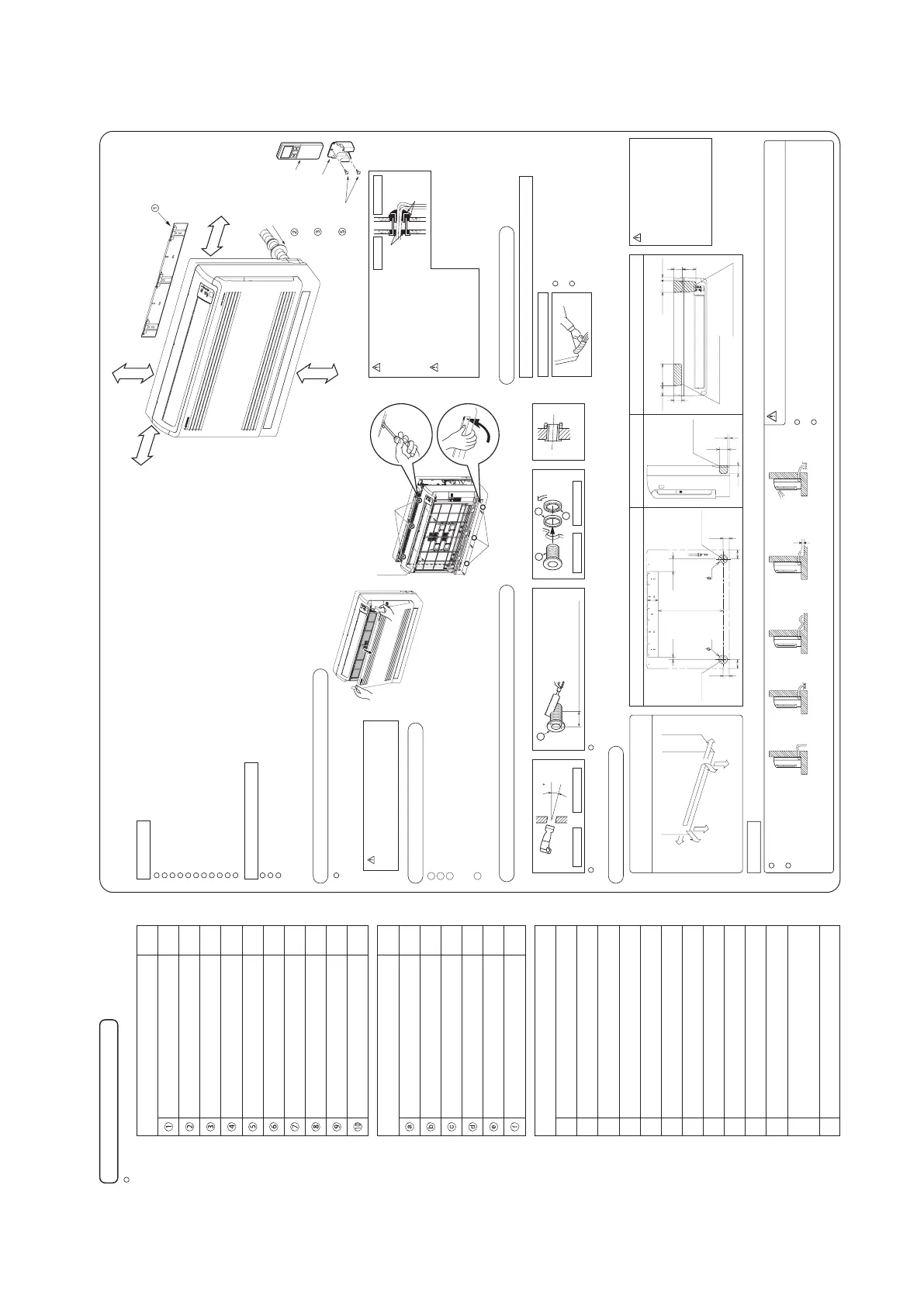
Necessary tools for the installation work
1
2
3
4
5
6
7
8
9
10
11
12
13
1
1
1
1
1
1
Q’ty
Locally procured parts
Sealing plate
Sleeve
Inclination plate
Putty
Drain hose (extension hose)
Piping cover
(for insulation of connection piping)
Plus headed driver
Knife
Saw
Tape measure
Hammer
Spanner wrench
Torque wrench
Hole core drill (65 mm in diameter
)
Wrench key (Hexagon) [4 mm
]
Flaring tool set
Gas leak detector
Pipe bender
Gauge for projection adjustmen
t
Used when flare is made by usin
g
conventional flare tool
()
)
14.0 – 61.0 N·m
(1.4 – 6.1 kgf·m)
(
Designed specifically
for R32 or R410A
)
1
1
1
9
2
2
2
2
1
2
Q’ty
Standard accessories (Installation kit)
Accessories for indoor unit
Installation board
(Attached to the rear of the indoor unit
)
Wireless remote control
Remote control holder
Battery [R03 (AAA, Micro) 1.5 V]
Air-cleaning filters
Filter holders
(Attached to the front panel of indoor unit
)
Pipe cover (200 mm)
Tapping screws
(for installation board ø4 X 25 mm)
Wood screws
(for remote control switch holder ø3.5 X 16 mm)
Band
()
Designed specifically
for R32 or R410A
Before
installation check that the power source matches the air-conditione
r.
Right
Rear
Downward
Left rear
Left downward
Left
60
15
60
60
22.785.3
100
55
157.276.3
For Right or Left rear piping For Right or Left piping
Right/Left
piping
For Right or Left bottom piping
Left bottom piping
Right bottom piping
SELECTION OF INSTALLATION LOCATION
INSTALLATION OF INDOOR UNIT
Indoor unit
Installing the support of piping
(Install at location that meets the following conditions, after getting approval from the customer)
Wireless remote control
In case of piping in the right rear direction
When drilling the wall that contains a metal lath, wire lath or metal plate, be sure to use pipe hole sleeve sold separately.
Taping of the exterior
Top
Thickness of the wall + 1.5 cm
5
ø65
Indoor side Outdoorside
Indoor side Outdoorside
Installed state
Turn to
tighten
b
b
c
a
Open and detachment of the air inlet panel
Drilling of holes and fixture of sleeve (Locally procured parts)
How to remove the front panel
Indoor unit piping direction
CAUTION
Drainage
The drain hose
tip is in water
Higher than
specified
Wavy The gap to the ground
is 5 cm or less
The drain hose tip
is in the gutter
Odor from
the gutter
Where there is no obstructions to the air flow and where the cooled and heated air can be evenly distributed.
A solid place where the unit or the wall will not vibrate.
A place where there will be enough space for servicing. (Where space mentioned right can be secured)
Where wiring and the piping work will be easy to conduct.
The place where receiving part is not exposed to the direct rays of the sun or the strong rays of the street lighting .
A place where it can be easily drained.
A place separated at least 1 m away from the television or the radio. (To prevent interference to images and sounds.)
Places where this unit is not affected by the high frequency equipment or electric equipment.
Avoid installing this unit in place where there is much oil mist.
Places where there is no electric equipment or household under the installing unit.
Install the indoor unit on flat wall.
A place where the air-conditioner can be received the signal surely during operating the wireless remote control.
Places where there is no affected by the TV and radio etc.
Do not place where exposed to direct sunlight or near heat devices such as a stove.
To open, pull the panel at both ends of upper
part and release latches, and undo the strings.
Then remove the panel.
When removing the air inlet panel, be
careful not to drop it on your feet.
CAUTION
Remove the air inlet panel.
Remove the 5 set screws.
Remove the 3 latches in the upper section.
If the latches are difficult to remove, push the latch portion out using a screw
driver, for example.
Move the lower part of the panel forward and remove the 6 latches in the
under section.
1
2
3
4
Installation board
5 cm minimum
from the wall
5 cm + Service space (30 cm)
from the wall
7 cm minimum from the ceiling
15 cm or below
from the floor
Sleeve
(sold separately)
Wireless remote
control
Remote control
holder
Wood
screws
CAUTION
Be careful not to stress the
connecting refrigerant
pipes. (Do not pull with a
force of larger than 5 kgf.)
If improperly installed, it
may cause abnormal noise
and vibration.
Latch
Latch
The screw of the lid is tightened securely.
Drill a hole with whole core drill. In case of rear piping draw out, cut off the lower
and the right side portions of the sleeve collar.
18.5 91.5
45
65
65
65
470
80
65
45
Right rear
piping
Left rear
piping
Piping is possible in the rear, left, left rear,
left downward, right or downward direction.
Tape only the portion that goes through
thewall.
Always tape the wiring with the piping.
Arrange the drain hose
in a downward angle.
Avoid the following
drain piping.
Pour water to the drain pan located under the heat exchanger, and ensure that
the water is discharged outdoor.
When the extended drain hose is indoor, securely insulate it with a heat insulator
available in the market.
Sufficient caremust be taken not to damage
the panel when connecting pipes.
Go through all installation steps and check if the drainage is all right.
Otherwise water leak may occur.
WARNING
putty
putty
Indoor sideOutdoor side
Completely seal the hole in the wall
with putty. If not sealed properly,
dust, insects, small animals, and
highly humid air may enter the room
from outside, which could result in
fire or other hazards.
CAUTION
Completely seal the hole in the wall
with putty. If not sealed properly,
furniture and other fixtures may be
damaged by water leakage or
condensation.
-
23
-
’20・SRF-DB-310D・
(860)
103.5
726
30.5
25.5
585
5
585
595
(600)
30.5
(238)
198
185
Installation of Installation board
Fixing on concrete wall
Use of nut anchor
Installation
board
Bolt
(M6 12)
Standard hole
Fixing of indoor unit
Floor installation Wall installation
Tapping screw
(860)
103.5
156.5
726
585
5
585
595
(600)
30.5
83.5
(238)
CAUTION
• During the installation, do not lean on the control box or the display, as they may be damaged.
• Install the indoor unit on flat wall. If improperly installed, it may cause abnormal noise and vibration. (Distortion on the wall shall be no larger than 3 mm.)
Secure using upper 2 screws for floor installations.
If possible, also attach two lower screws.
At first secure the installation board using 5 screws and the indoor unit using 2 screws.
Look for the inside wall structures (Intermediate
support or pillar and finally install the unit after
level surface has been checked.)
When practicing the half-console, make sure to fix the unit securely.
Otherwise, it could fall.
Adjustment of the installation board in the
horizontal direction is to be conducted with five
screws in a temporary tightened state.
Adjust so the board will be level by turning the
board with the standard hole as the center.
If there is an obstacle such as a
cable cover, cut off the hatched
part before installation.
Refrigerant
pipe
Slit
Refrigerant
pipe
Slit
Tape
Refrigerant
pipe
155
45
105
130
140
CONNECTION OF REFRIGERANT PIPINGS
Preparation
Indoor
(Do not turn)
Press
Remove
90s0.5˚
Dimension A (mm)
Liquid side φ6.35 : 9.1
Gas side
φ9.52 : 13.2
φ12.7 : 16.6
Measurement B
Flaring
block
Copper pipe
Connection
Finishing work and fixing
Insulation of the connection portion
Indoor
Liquid side
Gas side
(Do not turn)
Connection wiring,
Earth wiring
Outer tape
Refrigerant piping
Drain hose
Wood screw
Clamp
Install the removed flared nuts to the pipes to
be connected, then flared the pipes.
Remove the flared nuts. (on both liquid and
gas sides)
CAUTION
Do not apply refrigerating machine oil to the flared surface.
• Flaring work
Copper pipe
diameter
Conventional (R22) flare tool
φ6.35
φ9.52
φ12.7
0.0 - 0.5
0.0 - 0.5
0.0 - 0.5
1.0 - 1.5
1.0 - 1.5
1.0 - 1.5
1.5 - 2.0
1.5 - 2.0
2.0 - 2.5
Measurement B (mm)
Clutch type Wing nut type
Use a flare tool designed for R32, R410A or a conventional flare tool.
Note that measurement B (protrusion from the flaring block)
will vary depending on the type of a flare tool in use.
Keep the openings of the pipes covered with tapes etc.
to prevent dust, sand, etc. from entering them.
Connect the pipes on both liquid and gas sides.
Tighten the nuts to the following torque.
Liquid side (φ6.35) : 14.0 - 18.0 N·m (1.4 - 1.8 kgf·m)
Gas side (φ9.52) : 34.0 - 42.0 N·m (3.4 - 4.2 kgf·m)
(φ12.7) : 49.0 - 61.0 N·m (4.9 - 6.1 kgf·m)
CAUTION
Do not apply excess torque to the flared nuts.
Otherwise, the flared nuts may check depending.
CAUTION
Be careful not to stress the connecting refrigerant
pipes. (Do not pull with a force of larger than 5 kgf.)
Cover the exterior portion with
outer tape and shape the piping
so it will match the contours of
the route that the piping to take.
Also fix the wiring and pipings to
the wall with clamps.
ELECTRICAL WIRING WORK
Preparation of indoor unit
Terminal block
Sensor
Fixing screw
Clamp
Wiring holder
Remove the fixing screw of clamp.
Connect the connecting wire securely to the terminal block.
1) Connect the connection wire securely to the terminal
block. If the wire is not affixed completely, contact will be
poor, and it is dangerous as the terminal block may heat
up and catch fire.
2) Take care not to confuse the terminal numbers for indoor
and outdoor connections.
Fix the connecting wire by wiring clamp.
Pass the connecting wire through the wiring holder.
1
2
3
4
H05RNR4G1.5 (example) or 245IEC57
H
05
R
N
R
4 or 5
G
1.5
Harmonized cable type
300/500 volts
Natural-and/or synth, rubber wire insulation
Polychloroprene rubber conductors insulation
Stranded core
Number of conductors
One conductor of the cable is the earth conductor
(yellow/green)
Section of copper wire (mm
2
)
Mounting of connecting wires
CAUTION
• During installation, do not lean on the control box or the
display, as they may be damaged.
• Pass the connecting wire securely through the wiring holder.
If it passeson the sensor, it may not detect suction
temperature and/or humidity.
• Earth wire shall be Yellow/Green (Y/G)
in color and longer than other AC wires
for safety reason.
• Cover the indoor unit’s flare-connected joints, after
they are checked for a gas leak, with an indoor unit
heat insulating material and then wrap them with a
tape with an attached pipe cover placed over the
heat insulating material’s slit area.
Use cables for interconnection wiring to avoid loosening of the wires.
CENELEC code for cables Required field cables.
Pass the refrigerant pipe
through the piping hole to
indoor side.
Arrange the pipes according
to the direction of piping.
Cover the coupling with insulator and then cover it with tapes.
Use an attached pipe cover for heat insulation.
Position it so that the slit area faces upward.
Add
band
10
Pipe cover
9
CAUTION
If heat insulation is insufficient, water leakage may
occur. In addition, the room temperature sensor
may give a false alert due to heat radiation from
the pipes.
A
Clutch type flare tool
for R32 or R410A
If a conventional flare tool is used, use a copper pipe gauge or a
similar instrument to check protrusion so that you can keep
measurement B to a correct value.
In case of faulty wiring connection, the indoor unit stops, and then
the run lamp turns on and the timer lamp blinks.
 Loading...