-
12
-
'21 • KX-T-380
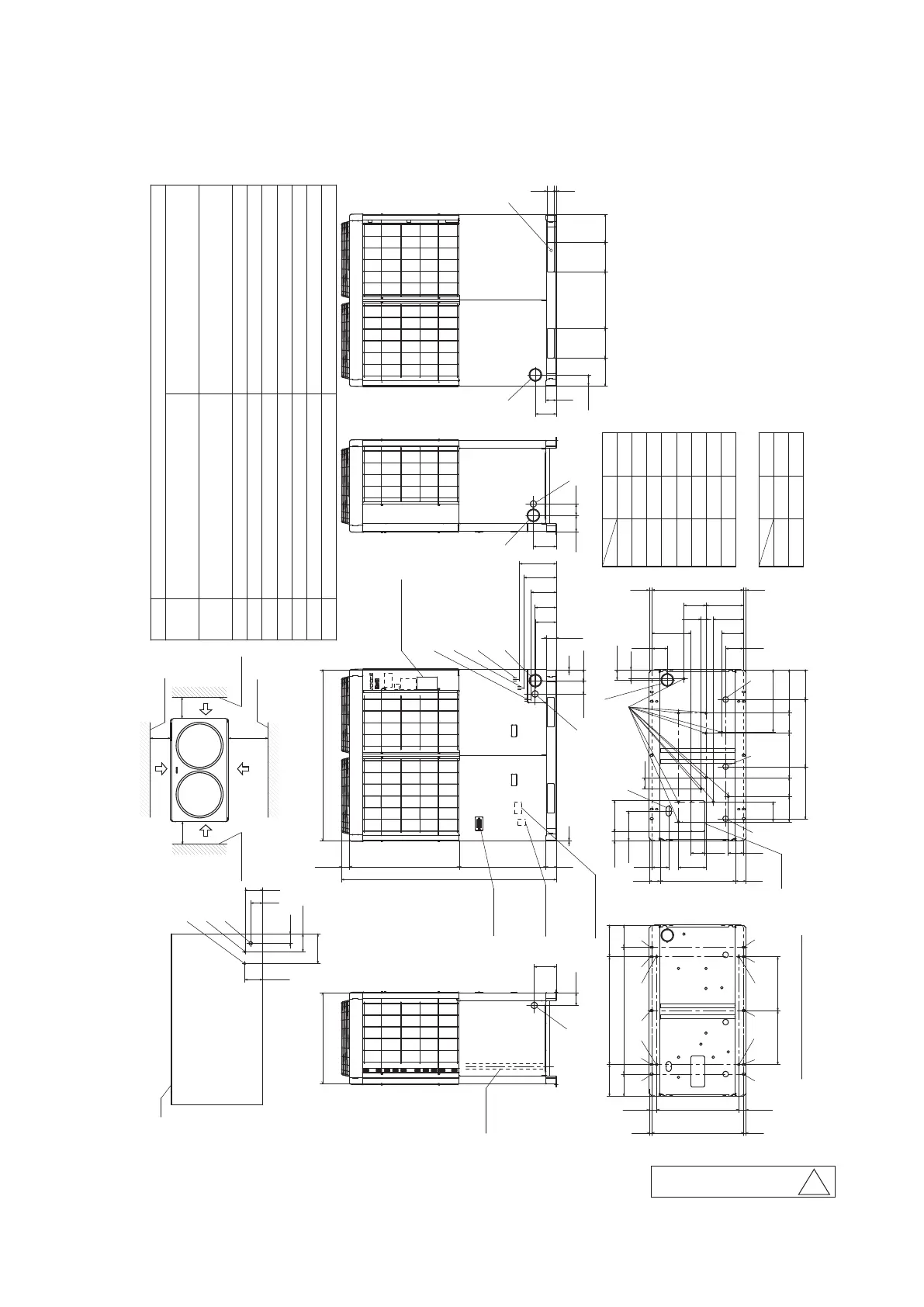
2.2 Exterior dimensions
Models FDC(S)280, 335(C)KXZA2
Back
142.5
75
AA
95
A
Wall height H2
Wall height H1
L1
H4
Wall height H4
H3
H2
L4
H1
L3
L2
Wall height H3
L4
L3
Installation
Dimensions
L1
L2
No limit
Open
100
No limit
1000
1500
10(30)
100
(Unit:mm)
10(30)
1
500
10(30)
2
For dimensions of anchor bolt hole
K
B
141.7
236
Dimensions of refrigerant piping connection pipe
(ichnography)
Drain hole
Drain waste water hose hole
Anchor bolt hole
Power source entry hole
Refrigerant piping exit hole
H
G
D
F
C
φ20,11 pcs.
φ45,3 pcs.
M10,4 pcs.
φ50(Right・Left・Front),Long hole 40
×
80(Bottom)
φ88(or φ100)
Refrigerant gas piping connection pipe
Mark
A
280:φ22.22(Brazing)
335:φ25.4(Brazing)
Content
L
K
Refrigerant oil equalization piping connection pipe
Carrying in or hole for hanging
230
×
60
φ9.52(Flare)
example
No limit
No limit
Open
Refrigerant liquid piping connection pipe
B
280:φ9.52(Flare)
335:φ12.7(Flare)
Unit:mm
( ): In case it is the promised installation location
that the outdoor unit is used on conditions with
the ambient temperature of 43℃ or more.
Open
Open
D(Left)
100
175
720 1350
Power source
connection
terminal box
D(Front)
291.6
AB
105
166
2
86
2
865.5
7-segment
display
Signal wire
connection
terminal box
64.5
B
C(Front)
A
169
Model name label
K
200.1
84
78.7
683
1697
C(Right)
128
182
D(Right)
90
166
450
86.5
230220 220230
L
C
(Back)
15 60
84
250
1000
(Position of anchor bolt of I)
647
(
Position of anchor bolt of F,J,M
)
72619
J
175
19
J
I
F
I
F
J
250850
I
F
I
F
175
J
58.5 58.5
M
M
(425) (425)
Air inlet
235
131
G
246
217
107
59485
72.5
85
H
174
720
530
342
295
238
410
352
G
148 158
235
22
140
G
306.7
D(Bottom)
80.5
120
22
71
200
170
119
494
40
C(Bottom)
87
158
MODEL
AA
AB
142.5
261
335
139.5
255
Dimensions
280
Installation space
( )
Service
space
Air inlet
Air inlet
Air inlet
Air inlet
PCB004Z522
B
※
Use I, J, M holes for customers for renovation.
 Loading...