-
196
-
'21 • KX-T-380
(1) Models FDC(S)280, 335, 475, 500, 560(C)KXZA2
8.7 Outdoor unit inverter PCB exchange procedure
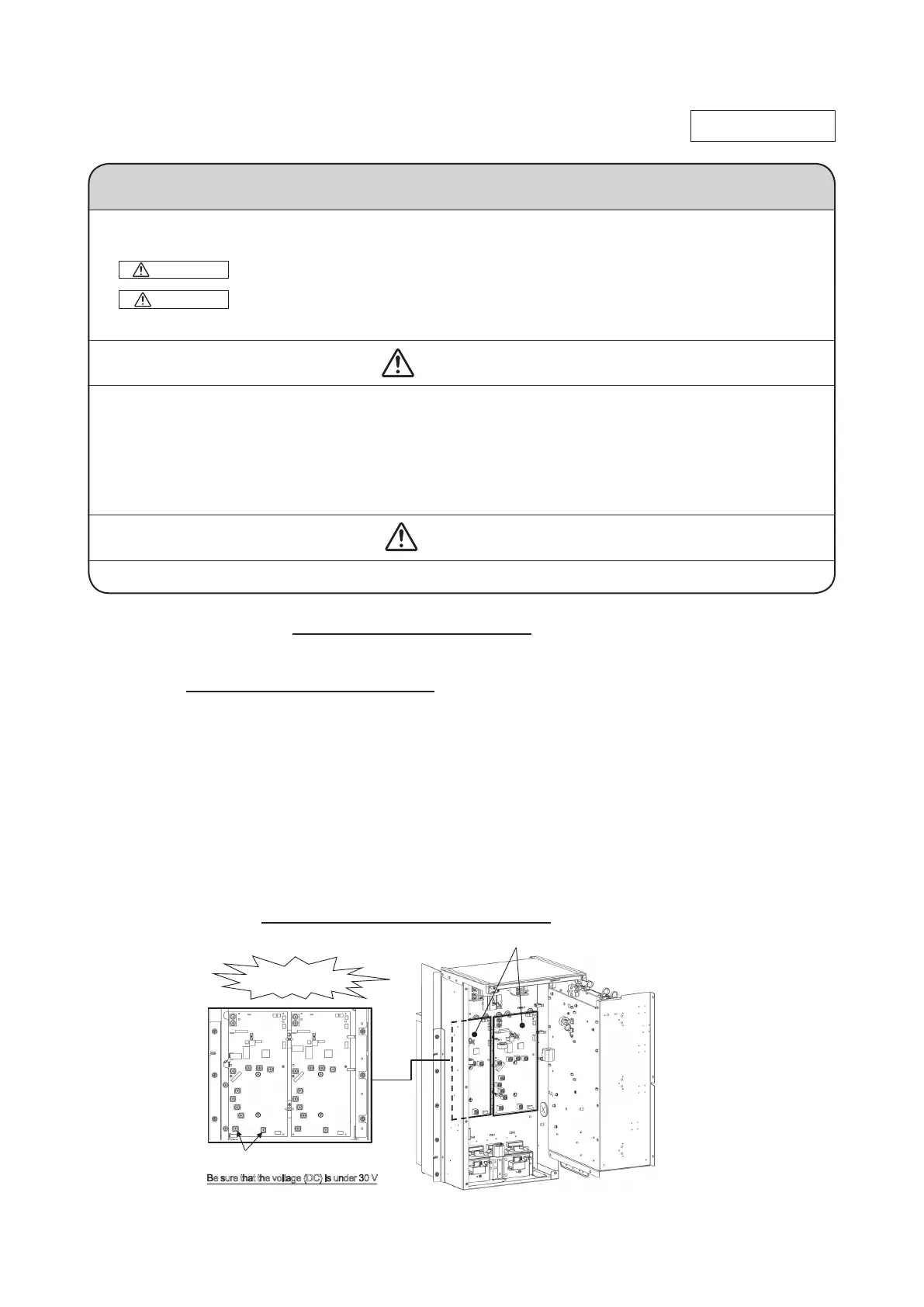
Exchange the Inverter PCB (Fig.1) according to the following procedure.
1. Exchange the PCB after elapsing 3 minutes from power OFF.
(Even after the breaker have been turned off, some capacitors still hold high voltage.
This condition is very dangerous to touch PCB.)
Be sure that the voltage (DC) is under 30 V before harnesses disconnect from PCBs.
(Refer to Fig.2.)
2.
Remove the connectors and wirings from the former Inverter PCB, and unscrew
the screw xing IGBT (IC2) to the radiator.
After removed the former PCB, wipe off the silicon grease neatly from the radiator.
3.
Match the switch (JSW10) of new PCB to the same setting as the former PCB.
4.
Attach the niplocker to new PCB front side and spacer to back side. (Refer to Fig.1.)
5.
Apply silicone grease evenly to the radiating surface of the IGBT (IC2) on the new PCB,
otherwise they might be damage. (Consume all of the silicon grease.)
Then install the new PCB in the same position as the former PCB.
6.
Tighten the screw of IGBT (IC2) on the new PCB and reconnect the connectors and
wirings as before. (Refer to table for recommended tightening torque regarding wirings
and screws.) (Be sure that there are not half inserted connectors.)
Precautions for Safety
• Since the following precaution is the important contents for safety, be sure to observe them.
WARNING and CAUTION are described as follows:
Indicates an imminently hazardous situation which will result in death or serious
injury if proper safety procedures and instructions are not adhered to.
Indicates a potentially hazardous situation which may result in minor or moderate
injury if proper safety procedures and instructions are not adhered to.
WARNING
• Securely exchange the PCB according to this procedure.
If the PCB is incorrectly exchanged, it will cause an electric shock or re.
• Be sure to check that the power source for the outdoor unit is turned OFF before exchanging the
substrate. The PCB exchange under current-carrying will cause an electric shock or re.
• After nishing the PCB exchange, check that wiring is correctly connected with the PCB before power
distribution. If the PCB is incorrectly exchanged, it will cause an electric shock or re.
CAUTION
• Band the wiring so as not to tense because it will cause an electric shock
WARNING
CAUTION
PCB012D108
Parts Ref.No. Tightening torque
IGBT IC2 2.5
-
2.7 N・m
Inverter PCB TB1-13 2.5
-
2.7 N・m
from power OFF
*Presence and shape of electric component
may vary according to model.
Fig.2 PCB mounting position and voltage measurement points
Table Recommended tightening torque
*Presence and shape of electric
component may vary according
to model.
Be sure that the voltage (DC) is under 30 V
Voltage (DC) measurement points
: TB6 and TB7 on the Inverter PCB
in half inserted
LED1
(Yellow)
 Loading...