-
14
-
'21 • KX-T-380
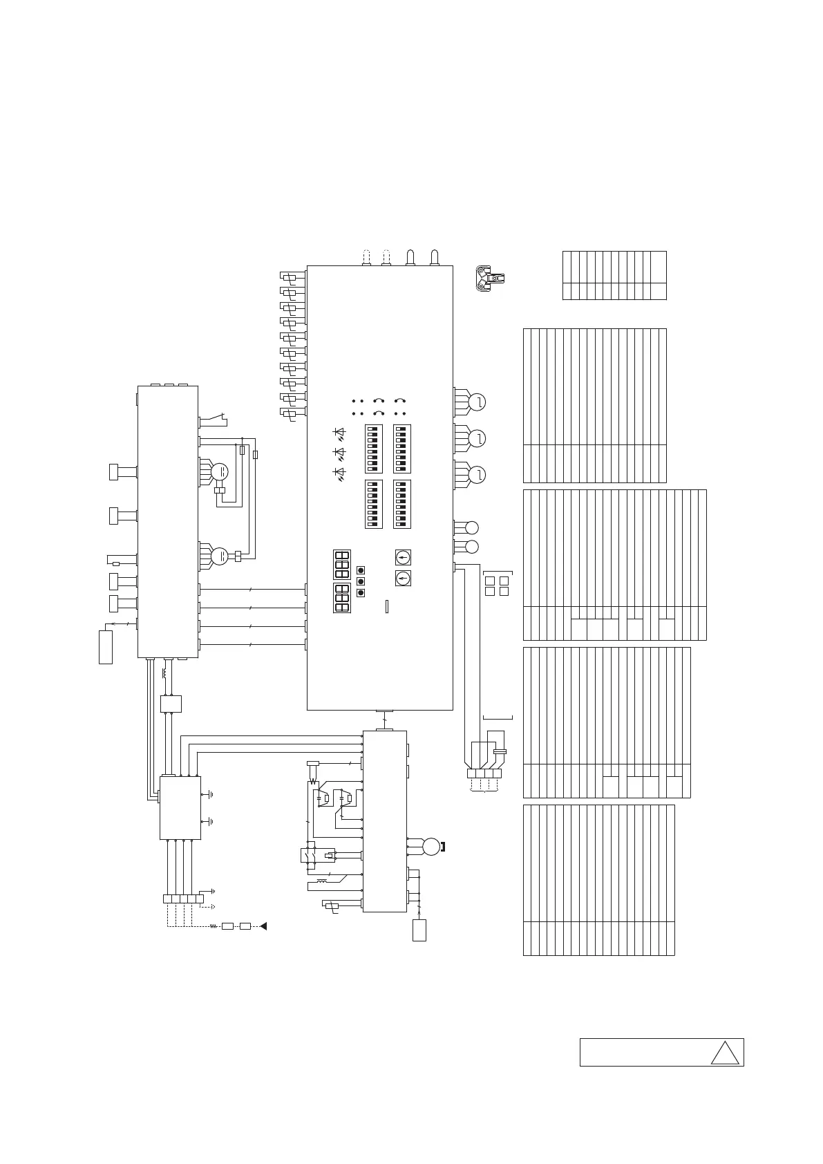
2.3 Electrical wiring
Models FDC(S)280, 335(C)KXZA2
Address setting switch(master・slave)
SW4-5 KXZE2 Model setting
SW5-1
SW5-2
SW5-3
SW4-8
SW4-7
SW4-6
ON
OFF
ON
OFF
Trial operationON
OFF
SW4-1−4 Model setting
Spare
Regular operation
Trial operation mode/cooling
Trial operation mode/heating
Pump down operation
Regular operation
Address setting switch(master・slave)
Fuse
Compressor motor
F
Crankcase heater
CH1
CM1
High pressure sensor
Low pressure sensor
PSL
CT1
PSH
SW2
Inspection LED reset
Auto backup operation
Regular operation
SW3-1
SW3-2
OFF
ON
Address setting SW outdoor unit No.(2 digits)
SW1
Defrost recover temperature
Defrost start temperature
External input select level
/pulse
D.C.reactor
Printed wiring board(PCB)PWB1−4
Set up model(volt)
Inspection(Red)LED1
LED2
LED3
J13
J14
J15
Address setting SW outdoor unit No.(1 digit)
Normal(Green)
Service(green for service)
SV1 Solenoid valve(CM1:bypass)
J16
Spare
SV6 Solenoid valve(Oil separator CM1)
SV11 Solenoid valve(Gas bypass)
Connector
Current sensor
Electrolytic capacitor
Expansion valve for heating
Expansion valve for SC
Blower motor
L1,L3
SpareSW3-3
Forced cooling/heating
Check operation
SW3-7 ON
OFF
SW3-5
OFF
ON
Regular operation
Regular operation
SpareSW3-6
KXZE2 Model settingSW5-4
SW5-5
OFF
ON Superlink communication
Superlink Ⅱ communication
SpareSW5-6−8
SpareSW6-1−3
SW6-4
OFF
ON High Head
Standard
SW3-8 Spare
Refrigerant quantity checkSW3-4
OFF
ON
Regular operation
Power transistor temperature sensor
7-segment indicate(ten's place)
Tho-P1
7-segment indicate(unit's place)
Tho-D1
Tho-H
SW8
SW9
TB1,2
4-way valve
Suction pipe temperature sensor
Tho-A
Tho-R3
Heat exchanger temperature sensor(inlet)
7SEG1
7SEG2
Tho-R4
Tho-S
Tho-SC
20S
7-segment L.E.D.(functionindication)
7-segment L.E.D.(dataindication)
52X1-1
Solenoid for CM
Tho-R1 Heat exchanger temperature sensor(exhaust)
Terminal block
External air temperature sensor
Tho-C1 Under-dome temperature sensor
Discharge pipe temperature sensor
Sub-cooling coil temperature sensor 2
Heat exchanger temperature sensor(exhaust)Tho-R2
Heat exchanger temperature sensor(inlet)
High pressure switch(for protection)63H1-1
Sub-cooling coil temperature sensor 1
Data clear/insertSW7
U(Red) V(White)
W(Blue)
Color marks
BK Black
BL
BR
GN
GY
OR
Blue
Brown
Green
Gray
Orange
RD
WH
YE
Red
White
Yellow
PK Pink
Yellow
YE/GN
/Green
Mark Color
Parts nameMark Parts nameMark Parts nameMark Parts nameMark
t° t° t° t°t°t° t°t°t° t°
t°
M M M
MM
SpareSW6-5−8
MS
3〜
Compressor
Terminal block
L3
TB1
L1
L2
N
Power source
Circuit
breaker
A1 B1
A2 B2
380V ,60Hz
BETWEEN INDOOR UNIT AND OUTDOOR UNIT,BETWEEN
OUTDOOR UNITS ON THE SAME REFRIGERANT LINE.
BETWEEN OUTDOOR UNITS ON THE DIFFERENT
REFRIGERANT LINES.
Earth leakage
breaker
(Impulse
withstanding type)
YE/GN
YE
CNX1
E
CNTH1 WH
RD
CNB2
BK
CNB3
RD
CNB4
WH
CNF1
GN
CNF2
BL
CNU1
Tho-A
Tho-S
Tho-D1
Tho-R1
Tho-R2
Tho-R3
Tho-R4
Tho-SC
Tho-H
Tho-C1
PSH
PSL
RD
WH
BK
CNL1 BL
RD
WH
BK
CNL2 WH
Cooling/Heating
forced input
Silent mode
input
External
input
Demand
input
CNG1 BL
CNG2 WH
CNS1 GN
CNS2 RD
TB6
N.F
PCB3-1
TB1
T4
RD
CN2
CN1
T3
TB7
TB8
TB2
TB3
T1
WH
BL
BK
TB2
A1
B1
A2
B2
CNSL1,2
WH
NETWORK CONNECTOR
Signal line
WH
BL
WH
BK
BK
RD
WH
BL
BK
WH
PCB1
CONTROL
SW2SW1
7SEG1 7SEG2
ON
OFF
1 2 3 3654 7 8 21 54 76 8
SW3 SW5
1 2 73 4 5 6 8
SW4
1 2 73 4 5 6 8
SW6
SW7SW8SW9
LED3LED1 LED2
CNV RD
J14
J12 J11
J16
J13
PC
J15
ON
OFF
Reserve
Trouble
output
Operation
output
CNZ1 RD
CNH BK
CNY WH
PCB4
POWER
CNN1 RD CNN2 YE
20S
SV6
CNN6 BK
SV1
CH1
CNR1 WH
BK
63H1-1
CNQ1 WH
CNE5 WH
CNA1 WH
CNW BK
CNM1 WH
4
PCB2-1
CNR2,CNR3
CNZ WH
BK
CNFAN4
GY
CNK2
BK
CNE2
BK
CNK4
CNN9 BK
SV11
L3
-
+
DS
~
~
BL
BL
RD
GY
14
8
4
7
BK
CNK3
BK
CNE1
GY
CNK1
BK
CNFAN3
CT1
Tho-P1
L1
WH
YE
YE
52X1-1
RD
+
C1-1
BL
1 2
3 4
5 6
2
2
2
GN GN
CNEEV1 RD
EEVSC
CNEEV2 BL
EEVH2
CNEEV3 WH
EEVH1
RD
BL
OR
YE
WH
RD
BL
OR
YE
WH
RD
BL
OR
YE
WH
RD
CNA3
CNFAN2 WH
FMo1 FMo2
CNFAN1 WH
F(4A)
BK
RD
F(4A)
RD
BK
BK
RD
WH
OR
YE
BL
GN
PK
WH
OR
YE
BL
GN
PK
RD
BK
R1-1
+
C1-2
WH
R1-2
V
U
W
CM1
RD
WH
BL
WH
CNI1
TB8 TB9 TB10
INV.
PCB2-1
TB1 TB2 TB3
WH
CNI2
CNR2 BK CNR3 BL
PCB4
CNM1
4
CNV WH CNZ WH
5
CNR1 CNC3CNIP
TB4 TB11 TB6TB5T11 T12
RDWHYE
RD
BL
BL
TB7
RD
4
BK
BK
RD BK
PCB004Z540
A