-
195
-
'21 • KX-T-380
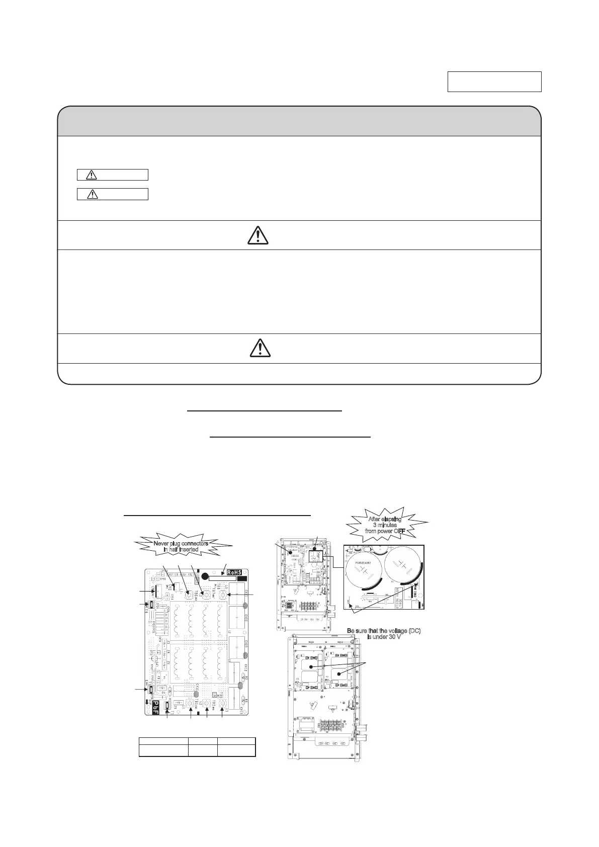
8.6 Outdoor unit noise filter PCB exchange procedure
Exchange the Noise Filter PCB (Fig.1) according to the following procedure.
1.
Exchange the PCB
after elapsing 3 minutes from power OFF
. (Even after the breaker
Have been turned off, some capacitors still hold high voltage. This condition is very
dangerous to touch PCB.)
Be sure that the voltage (DC) is under 30 V
before harnesses
disconnect from the PCBs. (Refer to Fig.2.)
2.
Disconnect the connectors and wirings from the former PCB and then exchange to
the new PCB.
3.
Reconnect the connectors and wirings as before.
(Refer to table for recommended tightening torque regarding wirings.)
(
Be sure that there are not half inserted connectors
.)
Precautions for Safety
• Since the following precaution is the important contents for safety, be sure to observe them.
WARNING and CAUTION are described as follows:
Indicates an imminently hazardous situation which will result in death or serious injury if
proper safety procedures and instructions are not adhered to.
Indicates a potentially hazardous situation which may result in minor or moderate injury if
proper safety procedures and instructions are not adhered to.
WARNING
• Securely exchange the PCB according to this procedure.
If the PCB is incorrectly exchanged, it will cause an electric shock or re.
• Be sure to check that the power source for the outdoor unit is turned OFF before exchanging the PCB. The
PCB exchange under current-carrying will cause an electric shock or re.
• After nishing the PCB exchange, check that wiring is correctly connected with the PCB before power distri
bution. If the PCB is incorrectly exchanged, it will cause an electric shock or re.
CAUTION
• Band the wiring so as not to tense because it will cause an electric shock
WARNING
CAUTION
PCB012D107
Parts Ref.No. Tightening torque
Noise Filter PCB
2.5
-
2.7 N・m
Voltage (DC) measurement points
: J101 and J102 on the Power PCB
T4
3 minutes
f
rom power OFF
Table Recommended tightening torque
electric component may
vary according to model.
Fig.2 PCB mounting position and
voltage measurement points
in half inserted
Be sure that the voltage (DC)
is under 30 V
 Loading...