-
17
-
'18 • SCM-T-251
4. CONNECTING PIPING WORK
1. Restrictions on unit installation
Abide by the following restrictions on unit installation.
Improper installation can cause compressor failure or performance degradation.
Model SCM40/45 Model SCM50/60
piping length
one indoor unit MAX 25m
all indoor unit MAX 30m
one indoor unit MAX 25m
all indoor unit MAX 40m
hight difference
MAX
25m
MAX 15m
MAX 15m
outdoor
unit
indoor
unit
indoor
unit
MAX
25m
MAX 15m
MAX 15m
outdoor
unit
indoor
unit
indoor
unit
indoor
unit
2. Preparation of connecting pipe
2.1. Selecting connecting pipe
Select connecting pipe according to the following table.
Indoor unit Model 20/25/35 Model 50/60
Gas pipe ø9.52 ø12.7
Liquid pipe ø6.35 ø6.35
• Pipe wall thickness must be greater than or equal to 0.8 mm.
• Pipe material must be O-type (Phosphorus deoxidized seamless copper pipe ICS 23.040.15, ICS
77.150.30).
2.2. Cutting connecting pipe
(1) Cut the connecting pipe to the required length with pipe cutter.
(2) Hold the pipe downward and remove the burrs. Make sure that no foreign material enters the pipe.
(3) Cover the connecting pipe ends with the tape.
3. Piping work
Check that both liquid and gas service valves are fully closed.
Carry out the piping work with service valves fully closed.
Liquid service valve
Gas service valve
3.1. Flaring pipe
(1) <SCM40/45>
Takeoutflarenutsfromtheservicevalvesofoutdoorunitandengagethemontoconnectingpipes.
<SCM50/60>
Takeoutflarenutsfromtheservicevalvesofoutdoorunit.
Ifa5.0,6.0kWclassindoorunit(gassidepipe12.7)isgoingtobeconnectedtotheservicevalves
(9.52), variable joints available as accessories must be applied to the gas side service valves.
Securelyfitthecopperpackingbetweentheservicevalveandthevariablediameterjointto prevent
shifting.
Engageflarenutsontoconnectingpipes.
Liquid side service valve ( 6.35)
6.35 pipe
50,60 model
Indoor unit
Gas side service
valve (
9.52)
Copper packing
Variable diameter joint
12.7 pipe
(2) Flarethepipesaccordingtotableandgureshownbelow.
Flare dimensions for R410A are different from those for conventional refrigerant.
AlthoughitisrecommendedtousethearingtoolsdesignedspecicallyforR410A,conventionalaring
toolscanalsobeusedbyadjustingthedimensionBwithaareadjustmentgauge.
Copperpipe
outer diameter
A
B
Copperpipe
outer diameter
B [Rigid (clutch) type]
R410A Conventional
ø6.35 9.1 ø6.35
0-0.5 1.0-1.5ø9.52 13.2 ø9.52
ø12.7 16.6 ø12.7
3.2. Connecting pipes
(1) Connect pipes on both liquid and gas sides.
<SCM40/45> <SCM 50/60>
Service valve
for room B
Service valve
for room A
Service valve
for room C
Service valve
for room B
Service valve
for room A
(2) Tightennutstospeciedtorqueshowninthetablebelow.
Service valve size (mm) Tightening torque (N·m)
ø6.35 (1/4") 14-18
ø9.52 (3/8") 34-42
ø12.7(1/2") 49-61
Do not hold the valve cap area with a spanner
CAUTION
• Donotapplyrefrigeratingmachineoiltothearedsurface.Itcancauserefrigerantleakage.
• Donotapplyexcesstorquetothearednuts.Thearednutsmaycrackresultinginrefrigerantleakage.
4. Evacuation
(1) Connect vacuum pump to gauge manifold. Connect charge hose of gauge manifold to a service port
of outdoor unit.
(2) Runthevacuumpumpforatleastonehourafterthevacuumgaugeshows-0.1MPa(–76cmHg).
(3) Confirmthatthevacuumgaugeindicatordoesnotriseevenifthesystemisleftfor15minutesormore.
Vacuum gauge indicator will rise if the system has moisture left inside or has a leakage point. Check
the system for the leakage point. If leakage point is found, repair it and return to (1) again.
(4) Close the Handle Lo and stop the vacuum pump.
Keep this state for a few minutes to make sure that the compound pressure gauge pointer does not
swing back.
(5) Remove valve caps from liquid operation valve and gas service valve.
(6)
(7)
Turn the liquid operation valve's rod 90 degree counterclockwise with a hexagonal wrench key to
open valve.
Close it after 5 seconds, and check for gas leakage.
Usingsoapywater,checkforgasleakagefromindoorunit'sareandoutdoorunit'sareandvalverods.
Wipe off all the water after completing the check.
Disconnectcharginghosefromgasservicevalve'sserviceportandfullyopenliquidandgasop-
eration valves. (Do not attempt to turn valve rod beyond its stop.)
(8) Tightenservicevalvecapsandserviceportcaptothespecifiedtorqueshowninthetablebelow.
Service valve size (mm)
Service valve cap tightening
torque (N·m)
Service port cap tightening
torque (N·m)
ø6.35 (1/4")
20-30
10-12ø9.52 (3/8")
ø12.7(1/2") 25-35
(9) Repeat the above steps (1) to (8) for all connected indoor units.
Handle Lo
Valve cap
Liquid service valve
Gas service valve
Service port
Pressure gauge
Gauge manifold
Handle Hi
Vacuum pump
CAUTION
Topreventvacuumpumpoilfromenteringintotherefrigerantsystem,useacounterowpreventionadapter.
5. ELECTRICAL WIRING WORK
WARNING
• Make sure that all the electrical work is carried out in accordance with the national or regional electri-
cal standards.
• Make sure that the earth leakage breaker and circuit breaker of appropriate capacities are installed
(Refer to the table given below).
•
Do not turn on the power until the electrical work is completed.
• Do not use a condensive capacitor for power factor improvement under any circumstances.
(It does not improve power factor. Moreover, it can cause an abnormal overheat accident).
Breakerspecications
Model Phase Earth leakage breaker Circuit breaker
SCM40/45/50/60 Single phase
Leakage current: 30mA,
0.1sec or less
Over current: 25A
Mainfusespecication
Model Specication Parts No.
SCM40/45 250V 15A SSA564A136
SCM50/60 250V 20A SSA564A136A
1.Preparing cable
(1) Selecting cable
Selectthepowersourcecableandconnectingcableinaccordancewiththespecicationsmentionedbelow.
(a) Power source cable
3-core* 2.5mm
2
ormore,conformedwith60245IEC57
When selecting the power source cable length, make sure that voltage drop is less than 2%.
If the wire length gets longer, increase the wire diameter.
(b) Connecting cable
4-core* 1.5mm
2
,conformedwith60245IEC57
* 1 Earth wire is included (Yellow/Green).
(2) Arrange each wire length as shown below.
Make sure that each wire is stripped 10mm from the end.
<Power source cable> <Connecting cable> <Wire end>
(3) Attach round crimp-type terminal to each wire as shown in the below.
Selectthesizeofroundcrimp-typeterminalafterconsideringthespecicationsofterminalblockandwire
diameter.
Round crimp-type terminal
Sleeve
CAUTION
Powersourcecableandconnectingcablemustconformtothespecicationsmentionedinthemanual.
Usingcableswithwrongspecicationsmayresultinunitmalfunction.
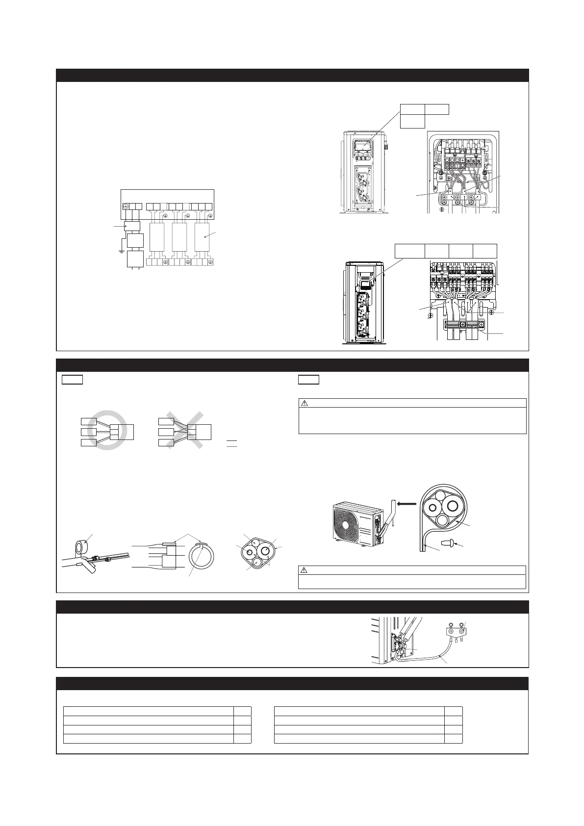
5. ELECTRICAL WIRING WORK
2.Connecting cable
(1) Remove the service cover and the terminal cover.
(2) Connectthecablesaccordingtotheinstructionsandguresgivenbelow.
(a) Connect the earth wire of power source cable.
An earth wire must be connected before connecting the other wires of power source cable.
Keep the earth wire longer than the remaining two wires of power source cable.
(b) Connect the remaining two wires (N and L) of power source cable.
(c) Connect the wires of connecting cables. Make sure that for each wire, outdoor and indoor side ter-
minal numbers match. Terminal number A of the outdoor unit is used for A indoor unit and terminal
number B for B indoor unit respectively.
Earth wire shall be Yellow/Green (Y/G) in color and longer than other wires for safety reason.
(3) Fasten the cables properly with cable clamps so that no external force may work on terminal connec-
tions.
Moreover, make sure that cables do not touch the piping, etc. When cables are connected, make sure
that all electrical components within the electrical component box are free of loose connector coupling
or terminal connection.
<Circuit diagram>
NL
Circuit
breaker
Earth
leakage
breaker
Earth
Power
Outdoor unit
Power
source
cable
Indoor unit
123
123
123
unit A
unit B
unit C
unit Aunit B
1 2 3 1 2 3 1 2 3
unit C
Connecting cable
<SCM40/45>
View of terminal block
unit A unit B
Power
source
<SCM 50/60>
View of terminal block
Power
source
unit A unit B unit C
6. FINISHING WORK
NOTE
●
Make sure to match the piping and wiring from each unit to the outdoor unit.
●
Be careful because if connections are wrong, normal operation cannot be achieved and may damage the
compressor.
Wiring
Indoor unit
unit C
unit B
unit A
Outdoor
unit
C
A
B
unit C
unit B
unit A
Outdoor
unit
C
A
B
1. Heating and condensation prevention
(1) Dress the connecting pipes (both liquid and gas pipes) with insulation to prevent it from heating
and dew condensation.
Use the heat insulating material which can withstand 120°C or higher temperature. Make sure that
insulation is wrapped tightly around the pipes and no gap is left between them.
(2) Wrap the refrigerant pipings of indoor unit with indoor unit heat insulation using tape.
(3) Covertheare-connectedjoints(indoorside)withtheindoorunitheatinsulationandwrapitwith
an insulation pad (standard accessory provided with indoor unit).
(4) Wrap the connecting pipes, connecting cable and drain hose with the tape.
(2) (3) (4)
Insulation pad
Position it so that the slit area faces upward.
Connecting cable
Liquid pip
e
Insulation
Tape
NOTE
Locationswhererelativehumidityexceeds70%,bothliquidandgaspipesneedtobedressed with20mm
or thicker heat insulation materials.
CAUTION
• Improper insulation can cause condensate(water) formation during cooling operation.
Condensate can leak or drip causing damage to household property.
• Poor heat insulating capacity can cause pipe outer surface to reach high temperature during heating
operation. It can cause cable deterioration and personal injury.
2.Finishing work
(1) Make sure that the exterior portion of connecting pipes, connecting cable and drain hose is wrapped
properly with tape. Shape the connecting pipes to match with the contours of the pipe assembly route.
(2) Fix the pipe assembly with the wall using clamps and screws. Pipe assembly should be anchored ev-
ery 1.5m or less to isolate the vibration.
(3) Install the terminal cover and the service cover securely. Water may enter the unit if service cover is
not installed properly, resulting in unit malfunction and failure.
Screw
CAUTION
Make sure that the connecting pipes do not touch the components within the unit. If pipes touch the
internal components, it may generate abnormal sounds and/or vibrations.
7. PUMP DOWN
(1) Connect charge hose of gauge manifold to a service port of outdoor unit.
(2) Close the liquid operation valves for all connected indoor units with hexagonal wrench key.
(3) Fully open the gas operation valves with hexagonal wrench key.
(4) Carry out forced cooling operation for all connected indoor units (For forced cooling operation procedure,
refer to indoor unit installation manual).
(5) When the low pressure gauge becomes 0.01MPa, close the gas service valves and stop forced cooling
operation.
Gauge manifold
Charge hose
Service port
8. INSTALLATIONTESTCHECKPOINTS
Afternishingtheinstallationwork,checkthefollowingpointsagainbeforeturningonthepower.
Conduct test run (Refer to indoor unit installation manual) and ensure that the unit operates properly.
Power source voltage complies with the rated voltage of air-conditioner.
Earth leakage breaker and circuit breaker are installed.
Powercableandconnectingcablearesecurelyxedtotheterminalblock.
Both liquid and gas service valves are fully open.
No gas leaks from the joints of the service valves.
Indoor and outdoor side pipe joints have been insulated.
Drainhose(ifinstalled)isxedproperly.
Screw of the service cover is tightened properly.
Connecting
cable
Power
source
cable
Cable clamp
Connecting
cable
Power
source
cable
Cable clamp
 Loading...