-
61
-
'18 • SCM-T-251
PFA004Z028
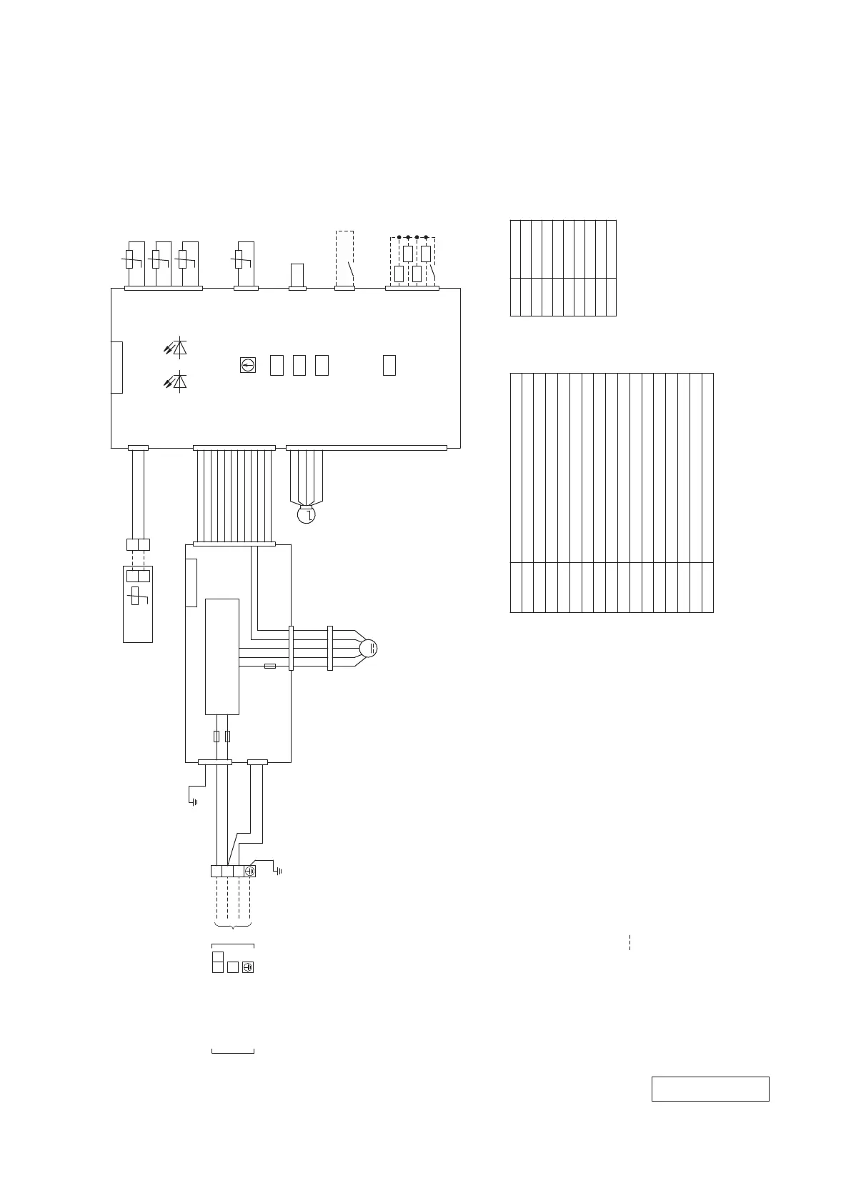
Notes 1. indicates wiring on site.
2. See the wiring diagram of outside unit about the line between
indoor unit and outdoor unit.
(0.3mm
2
X2)at remote control line. See spec
sheet of remote control in case that the total length is more than 100m.
4. Do not put remote control line alongside power source line.
Control PCB
Power PCB
XR1
XR2
XR3
XR4
Prepare on site
1
2
3
4
5
6
1
3
1
2
3
4
5
1
2
3
4
5
CNW2
WH
CNW1
WH
CNB
WH
CNN
YE
CNT
BL
F1(3.15A)
3
5
CNW0
WH
1
M
1
2
3
4
5
1
2
3
4
5
LM
6
7
8
9
10
11
12
13
14
15
16
17
18
19
20
CNJ
WH
Power circuit
(Operation)
(Heating)
(Compressor ON)
(Inspection)
6
7
8
9
10
11
12
6
7
8
9
10
11
12
WH
RD
WH
WH
WH
WH
WH
WH
WH
WH
WH
WH
WH
WH
BL
PK
BR
OR
RD
+12
X
Y
X
Y
t°
Remote
control
TB2
WH
BK
Thc
1
2
TB1
Earth
M
1 4 5 6 7
F3
(2.0A)
FM
i
CNM1
WH
1
2
3
4
5
6
t°
1
2
CNH
BK
Thi-A
t°
t°
t°
Thi-R1
Thi-R2
Thi-R3
BK
BK
BK
BK
BK
BK
CNTA
BL
1
2
YE/GN
3
BL
WH
1
3
CNW3
WH
F2(3.15A)
SW2
SW6
SW5
SW7
LED・2 LED・3
CNZ
FOR HA
WH
+12
BK
BK
Connecting line between
indoor unit and outdoor unit
21
3
Power source line
Signal line
XR5
(Remote operation:volt-free contact)
YE/GN
CNI
BL
WH
1 4 5 6 7
CNF1
WH
RD
1
2
Fan motor
Indication lamp(Red-Inspection)
ConnectorCNB-Z
LED・2
Model capacity settingSW6
Indication lamp(Green-Normal operation)
LED・3
SW2 Remote control communication address
SW5 Plural units Master/Slave setting
Fuse(Power PCB)F1-3
Sensor(Return air)
Sensor(Heat exchanger)
Sensor(Remote control)
Terminal block(Power source)TB1
Terminal block(Signal line)TB2
Louver motorLM
Operation check,drain motor test runSW7-1
Powerful mode Valid/Invalid
SW7-3
Meaning of marks
Parts nameMark
Thi-A
Thi-R1,2,3
Thc
FMi
Color marks
Mark
BK
BL
BR
OR
Color
Black
Blue
Brown
Orange
RD
WH
Red
White
Yellow
Yellow/Green
PinkPK
YE
YE/GN
(Remote operation:
volt-free contact)
RD
BK
WH
YE
BL
RD
BK
WH
YE
BL
(5) Ceiling suspended type (FDE)
Model FDE50VG
 Loading...