-
62
-
'18 • SCM-T-251
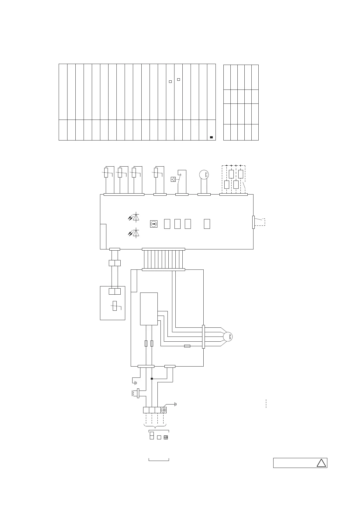
(6) Duct connected Low/Middle static pressure type (FDUM)
Model FDUM50VF
FS
FM
i
1
SW2
ConnectorCNB-Z
Meaning of marks
Drain motor
DM
TB1
Closed-end connector
SW6
Operation check, Drain motor test run
Powerful mode Valid/Invalid
SW7-3
SW7-1
Fuse
F1~3
Th
-R1,2,3
Th
-A
Thc
LED · E3
LED · E2
TB2
mark
Float switch
Indication lamp (Green-Normal operation)
Indication lamp (Red-Inspection)
Remote control communication address
Model capacity setting
Terminal block (Powerce) ( mark)
Terminal block (Signal line) ( mark)
Sensor (Remote control)
Sensor (Return air)
Sensor (Heat exchanger)
SW5
Plural units Master/Slave setting
Fan motor (with thermostat)
Earth
Power source line
Signal line
1 2
3
indoor unit and outdoor unit
Connecting line between
BL
3
1
WH
CNW3
WH
RD
RD
1
2
CNI
BL
CNR
WH
DM
FS
CNZ
For HA
WH
M
1
2
CNTA
BL
1
2
RD
t°
Control PCB
Power PCB
RD
YE
t°
YE
BK
t°
BK
1
2
3
4
5
6
BK
t°
BK
1
2
XR1
XR2
XR3
XR4
XR5 (Remote operation
(Remote operation input:
volt-free contact)
Prepare on site
1
2
3
4
5
6
+12
SW2
SW6
SW5
SW7
LED • E2 LED • E3
X
Y
1
3
X
Y
t°
TB2
WH
BK
WH
8
9
10
11
12
8
9
10
11
12
CNW2
WH
CNW1
WH
CNB
WH
CNN
YE
CNH
BK
CNT
BL
1
2
WH
RD
YE/GN
3
5
CNW0
WH
1
TB1
Power circuit
(Operation)
(Heating)
(Compressor ON)
(Inspection)
3
Th
C
Th -R1
Th
-R2
Th -R3
Th
-A
WH
WH
WH
WH
Remote control
i
i
i
i
i
i
input:volt-free contact)
WH
WH
WH
WH
WH
WH
WH
WH
3
4
5
6
7
1
2
5
6
7
2
3
4
1
M
1 4 5 6 7
RD BK WH YE BL
F3
(2A)
CNM1
WH
i
FM 1
F1 (3.15A)
F2 (3.15A)
CNWR2
WH
L
RD
YE/GN
RD
WH
ColorMark
BK
Color marks
Black
BL Blue
BR Brown
OR Orange
ColorMark
RD Red
WH White
YE Yellow
YE/GN Yellow/Green
L
Reactor
Notes 1. indicates wiring on site.
2. See the wiring diagram of outside unit about the line between
3. Use twin core cable (0.3mm
2
x
2) at remote control line.
inside unit and outside unit.
4. Do not put remote control line alongside power source line.
D
PJG000Z005
 Loading...