-
103
-
'19 • SCM-SM-281
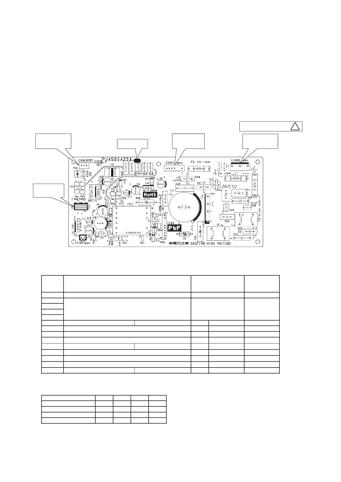
This PCB is a general PCB. Replace the PCB according to this instruction.
a)
Replace the PCB
①
Unscrew terminal of the wiring(yellow/green) connected to terminal block (CNWO) from the box.
②
Replace the PCB only after all the wirings connected to the connector are removed.
③
Fix the board such that it will not pinch any of the wires.
④
Reconnect the wirings to the PCB. Wiring connector color should match with the color of connector of the PCB.
⑤
Screw back the terminal of wiring, that was removed in ①.
b)
Power PCB
Parts mounting are different by the kind of PCB.
Part number
CNM1(White)
Fan motor
CNW1(White)
Control PCB
CNW3(White)
Terminal block
CNW0(White)
Terminal block
2) Power PCB
PSB012D992
C
●DIP switch setting list
SW2 0
SW6-1
SW6-2
SW6-3
SW6-4
SW7-1 OFF
SW7-2 OFF
SW7-3 OFF
SW7-4
SW8-1
SW8-2
SW8-3
SW8-4
OFFOFF
OFF
OFF
OFF
OFF
JSL1 With
Keep OFF
Keep OFF
Keep OFF
Keep OFF
Superlink terminal spare Normal
*
/switch to spare
Reserved
Anti-freeze control
Reserved
Reserved
Reserved
Reserved
Reserved
Keep OFF
Test run, drain motor Normal
*
/Test run
Valid/Invalid
*
Normal
Invalid
Model selection As per model See table 1.
Remark
Address No. setting at plural indoor units control by 1 R/C 0-F
Switch Description Default setting
Table 1: Indoor unit model selection with SW6-1-SW6-4
35VH 50VH 60VH
SW6-4
SW6-1
SW6-2
SW6-3
* Default settingNote(1) : SW8 : FDE only
OFF
OFF
OFF OFF
OFF
OFF
ON
25VH
OFF
OFF
ON
OFF
ON
ON
ON
ON
ON
Switch
Keep OFF
 Loading...