-
93
-
'19 • SCM-SM-281
(9) Checking the indoor electrical equipment
(a) Indoor unit PCB check procedure
Is there voltage between terminal
blocks
①
and
②
? (AC 220/230/240
V)
Indoor electrical components
unit
unit
unit
are normal.
Is the voltage between terminal
blocks
②
and
③
oscillating between
DC 0 and 20V?
Inspect power source
for outdoor unit.
Replace fuse.
Replace indoor unit PCB.
Is the fuse burnt out? (3.15 A)
YES
YES
YES
NO
NO
NO
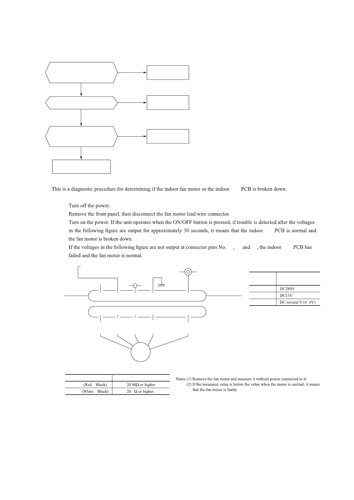
(b) Indoor fan motor check procedure
(i) Indoor unit PCB output check
① ④ ⑤
(ii) Fan motor resistance check
⑥⑤④③②①
⑥⑤④③②①
FM
i
DC15V
Indoor unit PCB
DC280V
DC several V
(4–6V)
CNU
(–)
GND
Blue
Yellow
White
Black
Red
Sensor
Operation
mode
Phenomenon
Shortcircuit Disconnected wire
Heat exchanger
sensor
Cooling
Heating
Ourdoor air
temperature sensor
Cooling
Heating
Discharge pipe
sensor
All modes
Measuring point Resistance when normal
①
−
③
−
④
−
③
−
Measuring
point
Resistance when
normal
①
−
③
④
−
③
⑤
−
③
Defrosting is performed for 10 minutes at approx. 40 minutes.
Defrosting is performed for 10 minutes at approx. 40 minutes.
k
1)
2)
3)
 Loading...