-
153
-
'19 • SCM-SM-281
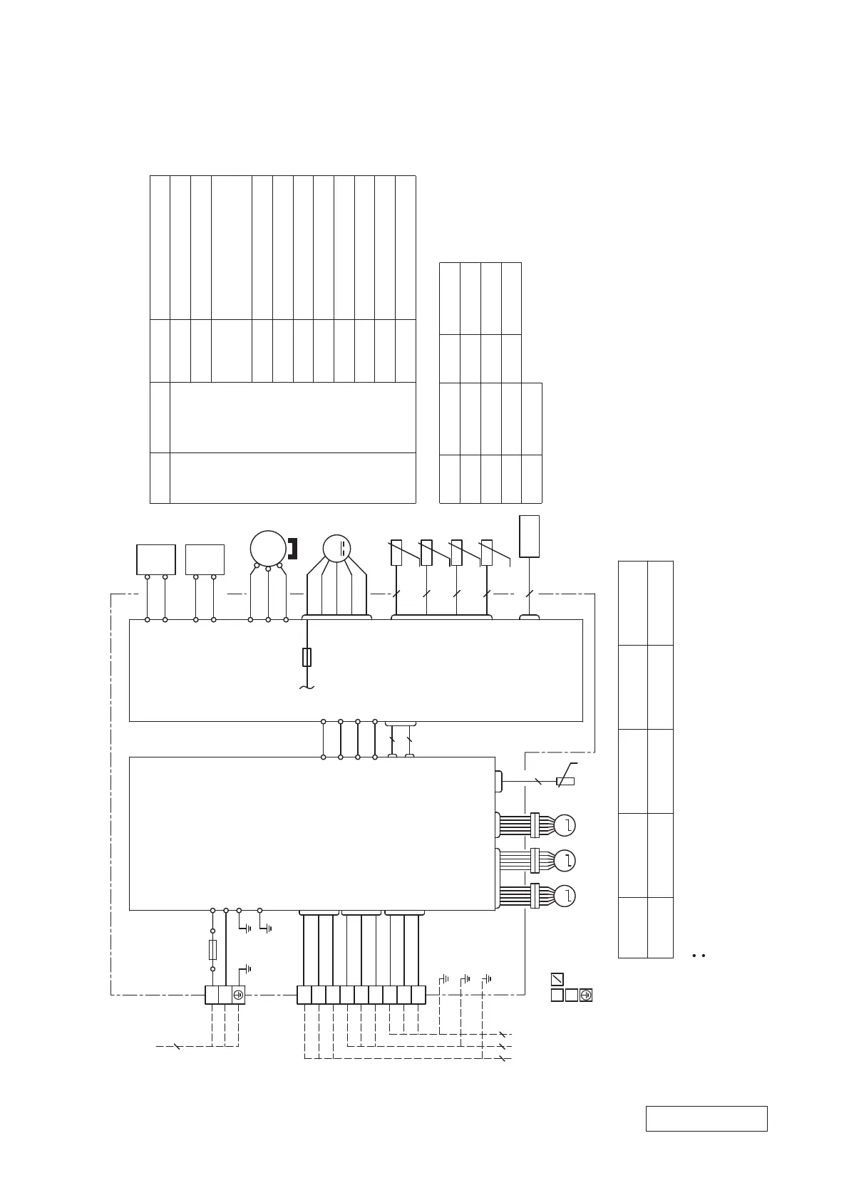
3. ELECTRICAL WIRING
(1) Outdoor units
Models SCM50ZS-W, 60ZS-W
RWC000Z333
BK
BR
Black
Brown
BL
YE
Blue
Yellow
RD
YG
Red
Yellow/Green
WH
White
YE
BL
T11
T12
WH
MS
EEV
A
WH
CNEEV1
(MAIN)
(SUB)
YE
BL
T1
T2
R-1
BK
RD
V
U
W
BK
3~
M
TH4
TH3
TH2
TH1
2
T 1A L 250V
F3
20S
CNTH
CNFAN
CN20S
RD
EEV
B
EEV
C
BL
CNEEV3
PCB 1
PCB 2
S-1
S-2
WH
WH
S-1
CNMAIN
RD
CNSUB
R
C-2
S
O
O
C-1
CN20V
3
2
L
L
2
FMo
CM
t゜
t゜
t゜
t゜
2
2
2
RD
EEV A,EEV B
L
Compressor motor
Reactor
Heat exchanger temperature sensor 1
Outdoor air temperature sensor
Discharge pipe temperature sensor
CM
TH1 (Tho-R1)
Connector
20S
4-way valve(coil)
Suction pipe temperature sensor
FMo
Fan motor
EEV C
CN20S
CNEEV1
CNEEV3
CNA
CNB
CNC
CNTH
CNMAIN
CN20V
CNSUB
CNFAN
Electric expansion valve(coil)
CNTH
2
t゜
TH5
S
R
BK
WH
IN
IN
G1
YG
WH
BK
Power cable
Signal wire
Earth wire
1
3
TB2
CNA
CNB
CNC
UNIT A
3
2
1
BK
WH
RD
3
2
1
3
2
1
BK
WH
BR
BK
WH
BL
G2
TB1
Power
source
3
UNIT B
UNIT C
44 4
T 20A E 250V
F4
N
L
YG
YG
Heat exchanger temperature sensor 2
TH5 (Tho-R2)
TH2 (Tho-A)
TH3 (Tho-D)
TH4 (Tho-S)
Terminal block
TB1,TB2
Model name
2.5mm x 3 17 1.5mm x 415
2
2
Power cable, indoor-outdoor connecting wires
Switchgear or circuit breaker capacity should be chosen according to national or regional electricity regulations.
The power cable specifications are based on the assumption that a metal or plastic conduit is used with no more than
three cables contained in a conduit and a voltage drop is 2
%. For an installation falling outside of these conditions,
please follow the national or regional electricity regulations.
The wire numbers include earth wire(Yellow/Green)
*
SCM50ZS-W
2
N
SCM60ZS-W
MAX running current Power cable
wire size x number*(A)
Power cable length
(m)
Connecting cable
wire size x number*
Power source
1 Phase
220-240V 50Hz
220V 60Hz
Item
Meaning of marks
Description
Item Description
Mark
Color marks
Color Mark Color
M M M
 Loading...