EasyManua.ls Logo

Mitsubishi Heavy Industries SCM60ZF-S User Manual

Mitsubishi Heavy Industries SCM60ZF-S
127 pages
To Next Page IconTo Next Page
To Previous Page IconTo Previous Page
Page #61 background imageLoading...
Page #61 background image
-
59
-
(3) Dew condensation prevention control for the cooling and dehumidifying operation
(STM, SRRM type only)
<I>
(a) Operation condition: During cooling or dehumidifying operation, 20 minutes elapsed after starting (with indoor command
speed something other than 0 rps), under the following conditions.
1) When the fan speed is set to “AUTO” or “HI”, or operation mode is set to “HI POWER”
(b) Detail of operation: The upper limit of the indoor command speed is set to the maximum number of revolutions at fan
speed “MED”.
(c) Rest conditions: Any one of the following conditions.
1) Fan speed set to anything other than “AUTO” or “HI”, or operation mode set to something other than “HI POWER”
2) 50 minutes elapsed after starting (with indoor command speed something other than 0 rps)
3) When indoor command speed is set to 0 rps
<II>
(a) Operation condition: During cooling or dehumidifying operation after starting (with indoor command speed set to some-
thing other than 0 rps), and all of the following conditions are satisfied.
1) When fan speed set to “AUTO” or “HI”, or operation mode to “HI POWER”.
2) When the indoor heat exchanger temp.(Th
I-R1) rises 5˚C or more relative to the lowest temperature within the first 3
minutes of operation.
(b) Detail of operation: The upper limit of the indoor command speed is set to the maximum number of revolutions at fan
speed “MED”.
(c) Rest conditions: Any one of the following conditions.
1) Fan speed set to anything other than “AUTO” or “HI”, or operation mode set to anything other than “HI POWER”
2) 30 minutes elapsed after this command starts
3) Indoor command speed set to 0 rps
(4) High pressure control
(a) Purpose: Prevents abnormally high pressure operation during heating.
(b) Detector: Indoor unit heat exchanger sensor (Th
I-R1)
(c) Detail of operation:
Notes (1) When the indoor unit heat exchanger temperature is in the range of B~C °C, the indoor command speed is reduced by 8 rps at each 20 seconds.
When the temperature is C °C or over for 1 minute continuously, the compressor is stopped.
(2) When the indoor unit heat exchanger temperature is in the range of A~B °C, if the indoor command speed is been maintained and the operation has
continued for more than 20 seconds at the same speed, it returns to the normal heating operation.
(3) Indoor blower retains the fan tap when it enters in the high pressure control. Outdoor blower is operated in accordance with the speed.
(4) 22~35 type: 20 rps. 50~60 type: 35 rps
¡ Temperature list
ABC
ThI-A
<
=
24 48.5 56 62
24 < ThI-A
<
=
27 47.5 53 61
27 < ThI-A 46.5 50 60
Unit : °C
(Example) Fuzzy
Indoor unit heat exchanger temperature (˚C)
Lower limit (4)
After lapse of 20 Sec. or over
(2)
After lapse of 20 Sec. or over
(2)
After lapse of 20 Sec. or over
(2)
B
C
8 rps
(1)
8 rps
0 rps
A

Table of Contents

Question and Answer IconNeed help?

Do you have a question about the Mitsubishi Heavy Industries SCM60ZF-S and is the answer not in the manual?

Mitsubishi Heavy Industries SCM60ZF-S Specifications

General IconGeneral
Cooling Capacity6.0 kW
Power Supply220-240 V, 50 Hz
Indoor Unit Dimensions (W x H x D)Varies depending on the indoor unit model selected
Weight (Indoor Unit)Varies depending on the indoor unit model selected
Indoor Unit Noise LevelVaries depending on the indoor unit model selected

Summary

GENERAL INFORMATION

Specific features

Details on piping length, connectable units, and inverter control.

How to read the model name

Explanation of the model naming convention for units.

SELECTION DATA

Specifications

Technical specifications for indoor and outdoor units, including capacities and dimensions.

Range of usage & limitations

Defines the operational limits for indoor and outdoor temperatures and piping.

Exterior dimensions

Provides detailed physical dimensions for indoor and outdoor units.

Piping system

Illustrates the refrigerant piping layout for different models.

Selection chart

Charts for correcting capacity based on temperatures and piping length.

ELECTRICAL DATA

Meaning of marks

Explains symbols used for components in outdoor and indoor units.

Electrical wiring

Wiring diagrams for indoor units, outdoor units, and remote controls.

OUTLINE OF OPERATION CONTROL BY MICROCOMPUTER

Operation control function by remote control switch

Details on using wireless and wired remote controls, unit indicators, and buttons.

Unit ON/OFF button

Explains the function of the unit's physical ON/OFF button.

Drain motor forced operation functions (STM, SRRM only)

Procedures for forced operation of the drain motor in specific models.

Power blackout auto restart function

Describes the function that resumes operation after a power cut.

Flap control (SKM, STM only)

Instructions on adjusting the air direction flap using the remote control.

Comfortable timer setting

Details on setting the comfortable timer for operation start time.

Cooling operation

Information on cooling operation modes and fan speed control.

Control and protection functions

Details various protective functions like frost prevention, overload, and compressor controls.

Heating operation

Information on heating operation modes and fan speed control.

Outline of automatic operation

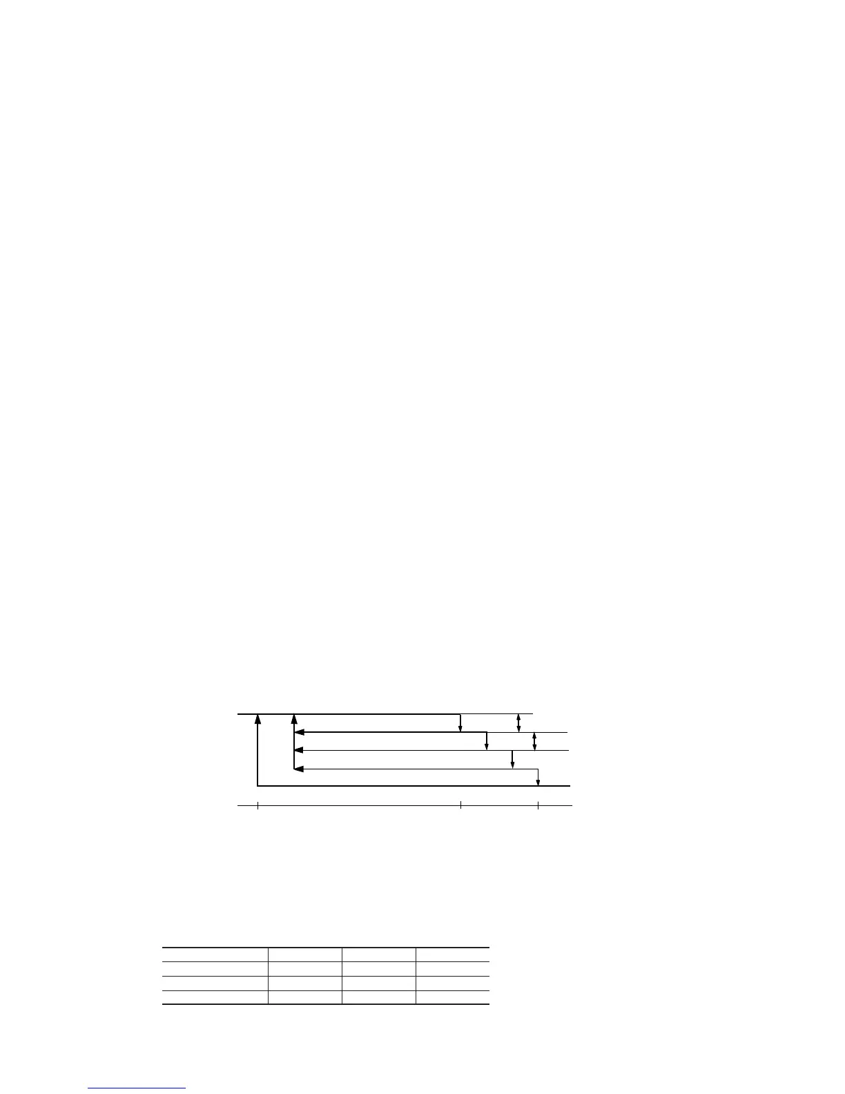
Explains how the unit determines and changes operation modes automatically.

Determining the operating mode

Illustrates how operating modes are determined and switched.

External control (remote display) /control of input signal (STM, SRRM only)

Covers external control outputs and input signal control for specific models.

Operation permission/prohibition control (STM, SRRM only)

Explains how to control operation using jumper wires and external signals.

APPLICATION DATA

SAFETY PRECAUTIONS

Critical safety warnings and cautions for installation and handling.

Installation of indoor unit

Instructions for mounting and installing various indoor unit types (SKM, STM, SRRM).

Installation of remote control

Procedures for installing the remote control and its accessories.

Installation of outdoor unit

Guidelines for selecting installation location and mounting outdoor units.

Electrical wiring

Instructions for connecting power lines and crossover wires for units.

Refrigerant Piping

Information on pipe limits, diameters, connection, and additional charge.

Test run and handling instruction

Steps for performing test runs and initial handling after installation.

Installation of optional parts (Ducted type)

Instructions for installing optional ducted type parts like grilles and filters.

MAINTENANCE DATA

Trouble shooting

Comprehensive guide for diagnosing and resolving operational issues with self-diagnosis.

Servicing

Procedures for evacuation and refrigerant charging during servicing.

REFRIGERANT PIPING INSTALLATION/SERVICING MANUAL FOR AIR CONDITIONERS USING R410A

Outline

Information on R410A refrigerant, its characteristics, and safety.

Safety during installation/servicing

Precautions for safe installation and servicing with R410A.

Refrigerant piping installation

Details on piping materials, joints, processing, and brazing for R410A.

Installation, removal and servicing

Covers tools for R410A, new installation, replacement, and retrofitting.

Refrigerant recovery

Procedures and tools for recovering R410A refrigerant safely.

Related product manuals