'09•SRK-DB-087D
(9) Checking the indoor electrical equipment
(a) Indoor PCB check procedure
(b) Outdoor unit
Is there voltage between terminal
blocks
①
and
②
? (AC 220/230/240
V)
Indoor electrical components
are normal.
Is the voltage between terminal
blocks
②
and
③
oscillating between
DC 0 and 20V?
Inspect power source
for outdoor unit.
Replace fuse.
Replace indoor PCB.
Is the fuse burnt out? (3.15 A)
YES
YES
YES
NO
NO
NO
(b) Indoor unit fan motor check procedure
1) Indoor PCB output check
① ④ ⑤
2) Fan motor resistance check
⑥ ⑤ ④ ③ ② ①
⑥ ⑤ ④ ③ ② ①
FM
I
DC15V
Indoor PCB
DC 308~336V
DC several V
(4~6 V)
CNU
(–)
GND
Blue
Yellow
White
Black
Red
Sensor
Operation
mode
Phenomenon
Shortcircuit Disconnected wire
Heat exchanger
sensor
Cooling
Heating
Ourdoor air
temperature sensor
Cooling
Heating
Discharge pipe
sensor
All modes
Measuring point Resistance when normal
①
−
③
−
④
−
③
−
Measuring
point
Resistance when
normal
①
−
③
④
−
③
⑤
−
③
⑥
−
③
Defrosting is performed for 10 minutes at approx. 45 (models 50, 60 : 35) minutes.
Defrosting is performed for 10 minutes at approx. 45 (models 50, 60 : 35) minutes.
'09•SRK-DB-087D
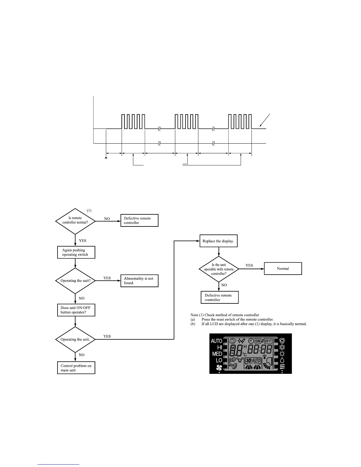
(10) How to make sure of wireless remote controller
(C) Power transistor inspection procedure
[Use a tester with a needle indicator for the inspection. (Do not use a digital tester. Check in the AC 300 volt range.)]
(1) If there is a self-diagnosis display, inspect the compressor system (burns, wiring mistakes, etc.) If no problems are found, check the
output of the power transistor.
(2) Output inspection procedure
Disconnect the terminals for the compresseor.
If an output such as the one shown in the figure on the below can be measured, the power transistor and the circuit board for the
outdoor unit are normal.
(Example)
RUN light : ON
TIMER light: 2 time flash
Measure in this section
Operation SW ON
8~10 sec. 1 sec. 1 sec.
3 min. 3 min.
1 sec.
0
Output voltage
(ACV)
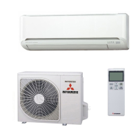
The figare below shows the SRK series.
 Loading...