'09•SRK-DB-087D
(a)
Inspection of electronic expansion valve
(OHFWURQLF H[SDQVLRQYDOYHRSHUDWHVIRUDSSUR[VHFRQGVDIWHUWKHSRZHURQLQRUGHUWRGHWHUPLQHLWVDSHUWXUH&KHFNWKH
RSHUDWLQJVRXQGDQGYROWDJHGXULQJWKHSHULRGRIWLPH9ROWDJHFDQQRWEHFKHFNHGGXULQJRSHUDWLRQLQZKLFKRQO\WKHDSHUWXUH
FKDQJHRFFXUV
,ILWLVKHDUGWKHVRXQGRIRSHUDWLQJHOHFWURQLFH[SDQVLRQYDOYHLWLVDOPRVWQRUPDO
,IWKHRSHUDWLQJVRXQGLVQRWKHDUGFKHFNWKHRXWSXWYROWDJH
6
White
Yellow
Orange
Blue
Red
5 4
3
2
1
([SDQVLRQYDOYHFRQQHFWRU
3EODFN
$SSUR[9LVGHWHFWHGIRUVHFRQGVDIWHUWKHSRZHURQ
,IYROWDJHLVGHWHFWHGWKHRXWGRRU3&%LVQRUPDO
,IWKHH[SDQVLRQYDOYHGRHVQRWRSHUDWHQRRSHUDWLQJVRXQGZKLOHYROWDJHLVGHWHFWHGWKHH[SDQVLRQYDOYHLVGHIHFWLYH
• Inspection of electronic expansion valve as a separate unit
0HDVXUHWKHUHVLVWDQFHEHWZHHQWHUPLQDOVZLWKDQDQDORJWHVWHU
Measuring point Resistance when normal
±
DW&
±
±
±
(b)
Outdoor unit fan motor check procedure
:KHQWKHRXWGRRUXQLWIDQPRWRUHUURULVGHWHFWHGGLDJQRVHZKLFKRIWKHRXWGRRUXQLWIDQPRWRURURXWGRRU3&%LVGHIHFWLYH
'LDJQRVHWKLVRQO\DIWHUFRQ¿UPLQJWKDWWKHLQGRRUXQLWLVQRUPDO
2XWGRRU3&%RXWSXWFKHFN
7XUQRIIWKHSRZHU
'LVFRQQHFWWKHRXWGRRUXQLWIDQPRWRUFRQQHFWRU&1)$1
:KHQWKHLQGRRUXQLWLVRSHUDWHGE\LQVHUWLQJWKHSRZHUVXSSO\SOXJDQGSUHVVLQJ21WKHEDFNXSVZLWFKIRUPRUHWKDQ
VHFRQGVLIWKHYROWDJHRISLQ1R
②
LQWKHIROORZLQJ¿JXUHLVRXWSXWIRUVHFRQGVDWVHFRQGVDIWHUWXUQLQJ³21´WKH
EDFNXSVZLWFKWKHRXWGRRU3&%LVQRUPDOEXWWKHIDQPRWRULVGHIHFWLYH
,IWKHYROWDJHLVQRWGHWHFWHGWKHRXWGRRU3&%LVGHIHFWLYHEXWWKHIDQPRWRULVQRUPDO
1RWH7KHYROWDJHLVRXWSXWWLPHVUHSHDWHGO\,ILWLVQRWGHWHFWHGWKHLQGRRUXQLWGLVSOD\VWKHHUURUPHVVDJH
2) Fan motor resistance check
1RWHV5HPRYHWKHIDQPRWRUDQGPHDVXUHLWZLWKRXWSRZHUFRQQHFWHGWRLW
1RWHV,IWKHPHDVXUHGYDOXHLVEHORZWKHYDOXHZKHQWKHPRWRULVQRUPDOLWPHDQV
WKDWWKHIDQPRWRULVIDXOW\
Measuring point Resistance when normal
⑥
−
④
5HG
−
%ODFN 0RUKLJKHU
③
−
④
:KLWH
−
%ODFN 0RUKLJKHU
Measuring
point
Resistance when
normal
⑥
−
④
'&a9
③
−
④
'&9
②
−
④
'&VHYHUDO9a9
①
−
④
'&VHYHUDO9a9
DC15V
DC several (4~7V)
Outdoor PCB
GND
(−)
DC308~336V
CNFAN
Red
Black
White
Yellow
Blue
①②③④⑤⑥
①②③④⑤⑥
FM0
11.2
FDTC series
11.2.1
Diagnosing of microcomputer circuit
(1) Selfdiagnosis function
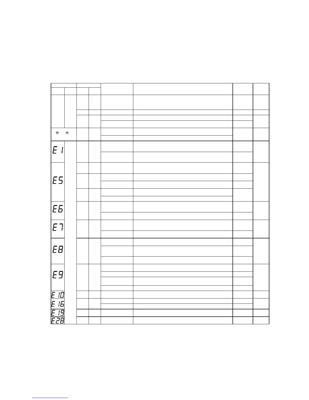
(a) Check indicator table
Whether a failure exists or not on the indoor unit can be know by the contents of remote controller error code, indoor unit
green LED (power pilot lamp and microcomputer normality pilot lamp) or red LED (check pilot lamp).
(i) Indoor unit
Remote controller Indoor control PCB
Location of trouble Description of trouble Repair method
Reference
page
Error code Red LED Red LED
Green
LED (1)
No-indication
Stays OFF
Stays OFF
Keeps
flashing
—
• Normal operation
—
—
Stays OFF Stays OFF Indoor unit power supply • Power OFF, broken wire/blown fuse, broken transformer wire Repair
217
*
3 times
flash
Keeps
flashing
Remote controller wires • Poor connection, breakage of remote controller wire * For wire breaking at power ON, the LED is OFF. Repair
218
Remote controller • Defective remote controller PCB
Replacement of
remote controller
or
INSPECT I/U
Stays OFF
Keeps
flashing
Indoor-outdoor units connection
wire
• Poor connection, breakage of indoor-outdoor units connection wire
Repair
219 ~ 223
Remote controller • Improper setting of master and slave by remote controller
Keeps
flashing
Stays OFF
*
Keeps
flashing
Remote controller wires (Noise)
• Poor connection of remote controller signal wire (White)
• Intrusion of noise in remote controller wire
*
For wire breaking at power ON, the LED is OFF
Repair
224
Remote controller indoor control
PCB
*• Defective remote controller or indoor control PCB (defective communication circuit)?
Replacement of
remote controller or
PCB
2 times
flash
Keeps
flashing
Indoor-outdoor units connection
wire
• Poor connection of wire between indoor-outdoor units during operation
(disconnection, loose connection)
• Anomalous communication between indoor-outdoor units by noise, etc.
Repair
225
2 times
flash
Keeps
flashing
(Noise) • CPU-runaway on outdoor control PCB
Power reset or
Repair
Outdoor control PCB
*• Occurrence of defective outdoor control PCB on the way of power supply (defective communication
circuit)?
Replacement of
PCB
2 times
flash
Keeps
flashing
Outdoor control PCB • Defective outdoor control PCB on the way of power supply
Replacement
Fuse • Blown fuse
1 time flash
Keeps
flashing
Indoor heat exchanger tempera-
ture thermistor
• Defective indoor heat exchanger temperature thermistor (defective element, broken wire,
short-circuit)
• Poor contact of temperature thermistor connector
Replacement, repair
of temperature
thermistor
226
Indoor control PCB
*• Defective indoor control PCB (Defective temperature thermistor input circuit)?
Replacement of
PCB
1 time flash
Keeps
flashing
Indoor return air temperature
thermistor
•
Defective indoor return air temperature thermistor (defective element, broken wire, short-circuit)
• Poor contact of temperature thermistor connector
Replacement, repair
of temperature
thermistor
227
Indoor control PCB
*• Defective indoor control PCB (Defective temperature thermistor input circuit)?
Replacement of
PCB
1 time flash
Keeps
flashing
Installation or operating condi-
tion
• Heating over-load (Anomalously high indoor heat exchanger temperature) Repair
228
Indoor heat exchanger tempera-
ture thermistor
• Defective indoor heat exchanger temperature thermistor (short-circuit)
Replacement of
temperature therm-
istor
Indoor control PCB
*• Defective indoor control PCB (Defective temperature thermistor input circuit)?
Replacement of
PCB
1 time flash
Keeps
flashing
Drain trouble • Defective drain pump (DM), broken drain pump wire, disconnected connector
Replacement, repair
of DM
229
Float switch • Anomalous float switch operation (malfunction) Repair
Indoor control PCB
*• Defective indoor control PCB (Defective float switch input circuit)
*• Defective indoor control PCB (Defective DM drive output circuit)?
Replacement of
PCB
Option • Defective optional parts (At optional anomalous input setting) Repair
Stays OFF
Keeps
flashing
Number of connected indoor
units
•
When multi-unit control by remote controller is performed, the number of units is over Repair
230
Stays OFF
Keeps
flashing
Fan motor • Defective fan motor Replacement, repair
231
Indoor control PCB • Defective indoor control PCB Replacement
1 time flash
Keeps
flashing
Indoor control PCB • Improper operation mode setting Repair
232
Stays OFF
Keeps
flashing
Remote controller temperature
thermistor
• Broken wire of remote controller temperature thermistor Repair
233
Note (1)
Normal indicator lamp (Indoor unit: Green) extinguishes (or lights continuously) only when CPU is anomalous. It keeps flashing
in any trouble other than anomalous CPU.
(2) * mark in the Description of trouble means that, in ordinary diagnosis, it cannot identify the cause denitely, and, if the trouble is repaired by replacing
the part, it is judged consequently that the replaced part was defective.
 Loading...