4D68 ENGINE (E-W) -
Pistons and Connecting Rods
11A-11-2
REMOVAL SERVICE POINTS
A
A
"
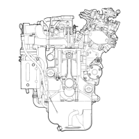
CONNECTING ROD CAP REMOVAL
(1) Mark the cylinder number on th e side of t he connecting
rod big end for correct reassembly.
INSTALLATION SERVICE POINTS
"
A
A
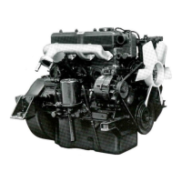
PISTON PIN / PISTON / CONNECTING ROD
INSTALLATION
(1) Assemble the piston and connecting rod, directing the
front marks in the same direction.
(2) Insert the piston pin. The pin should be inserted by hand.
Replace if there is a play.
"
B
A
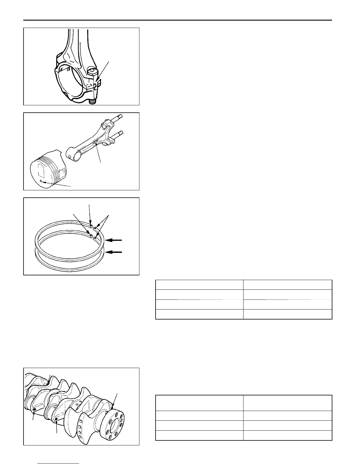
PISTON RING NO. 2 / PISTON RING NO. 1
INSTALLATION
(1) Using a ring expander, fit ring No. 2 a n d ring No. 1 with
their identification marks facing upward (on the piston
crown side).
Identification marks:
No. 1 ring: T
No. 2 ring: 2T
NOTE
Piston rings are stamped with size marks as follows:
Size Size mark
STD None
0.50 mm O.S. 50
1.00 mm O.S. 100
"
C
A
CONNECTING ROD BEARING INSTALLATION
(1) When the bearings are replaced, select an d install them
according to the identification colors on the crankshaft.
Crank pin O.D.
identification color
Connecting rod bearing
identification mark
Yellow 1
None 2
White 3
PWEE9609
E
Dec. 1996Mitsubishi Motors Corporation
DEN0050
Cylinder No.
DEN0784
Front mark
Front mark
(Identification
mark)
9EN0524
“T” identification mark
“2T” identification mark
Side mark
No. 1
No. 2
6EN0700
Location of identification
colors
No. 1
No. 2
No. 3
No. 4

 Loading...