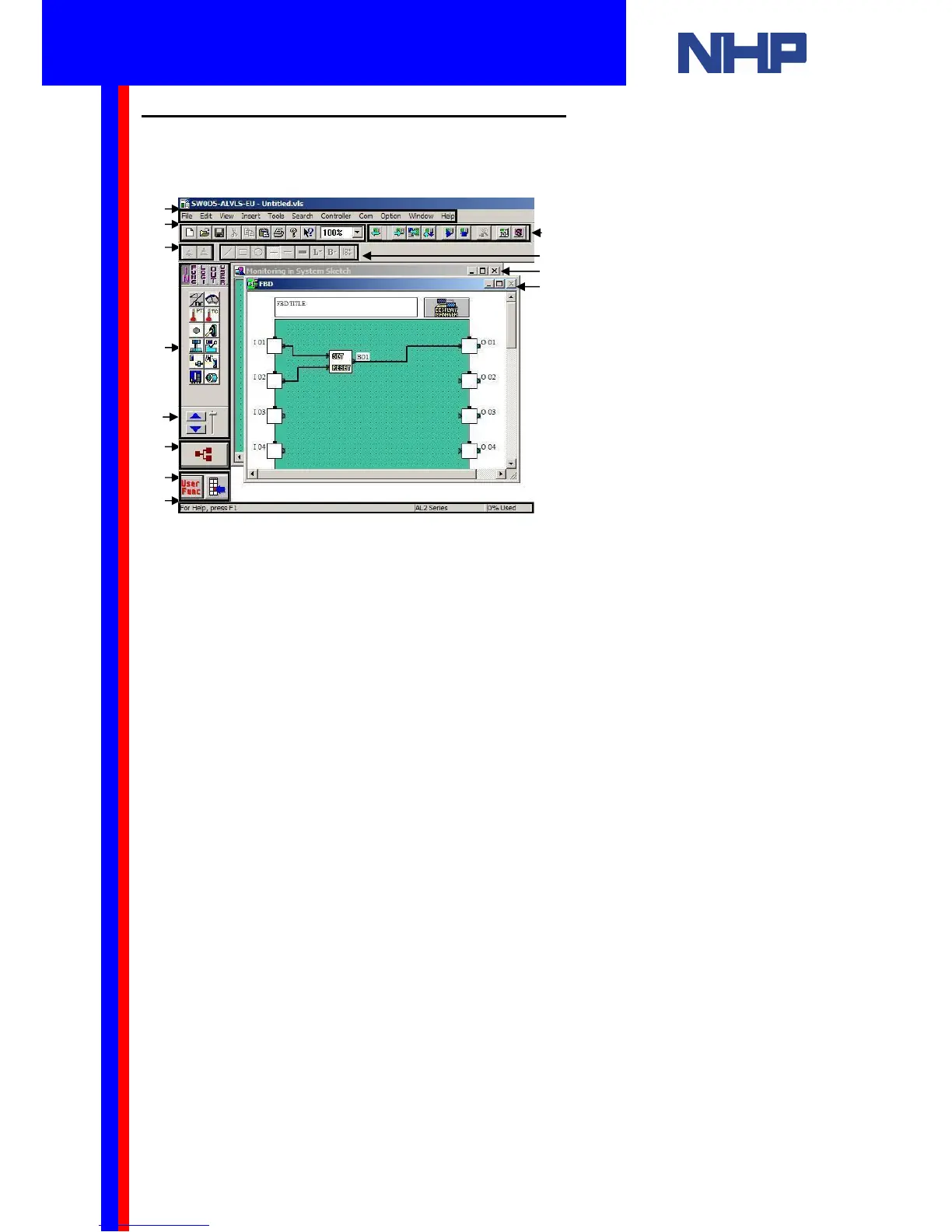
5.2 Visual Logic Programming Environment
Take this opportunity to familiarize yourself with the features of the Visual Logic’s
Programming environment.
Legend
1. Menu Bar
2. Standard Toolbar
3. Controller Toolbar
4. Image Toolbar
5. Drawing Toolbar
6. Accessories Toolbar
7. Wiring Tool
8. User Function Toolbar
9. System Sketch Monitor Window
10. Function Block Diagram (FBD) Window
11. Status Bar
12. Accessories Scroll button
You should see two windows: the Function Block Diagram (FBD) window and the System
Sketch Monitoring window. The next section will describe these windows.
Placing a function or logic block into your program is a simple matter of dragging the block
from the Accessories toolbar into the FBD Window.