Minimum amount of water required in the space
heating circuit
Outdoor heat pump unit Minimum water quantity [L]
Packaged model PUHZ-W50 40
PUHZ-W85 60
PUHZ-HW112 80
PUHZ-HW140 100
Split model PUHZ-RP35 32
PUHZ-RP50 40
PUHZ-RP60 50
PUHZ-(H)RP71 60
PUHZ-(H)RP100 80
PUHZ-(H)RP125 100
PUHZ-RP140 120
PUHZ-SW40 32
PUHZ-SW50 40
PUHZ-SW75 60
PUHZ-SW100 80
PUHZ-SW120 120
PUHZ-SHW80 60
PUHZ-SHW112 80
PUHZ-SHW140 100
<Table 4.2.1>
4.2 Water Quality and System Preparation
General
• Water quality should be to European Directive 98/83 EC standards.
► pH value of 6.5-8.0 (Recommended: pH6.5 - 7.5)
► Calcium ≤ 100 mg/l
► Chlorine ≤ 100 mg/l
► Iron/Manganese ≤ 0.5 mg/l
• In known hard water areas, to prevent/minimise scaling, it is benecial to restrict
the routine stored water temperature (DHW max. temp.) to 55°C.
Anti-Freeze
Anti-freeze solutions MUST use propylene glycol with a toxicity rating of Class 1 as
listed in Clinical Toxicology of Commercial Products, 5th Edition.
N
ote: Ethylene glycol is toxic and must N
OT be used in the primary water
circuit in case of any cross-contamination of the potable circuit.
New Installation (primary water circuit)
• Before connecting outdoor unit, thoroughly cleanse pipework of building debris,
solder etc using a suitable chemical cleansing agent.
•
Flush the system to remove chemical cleanser.
• For all packaged model systems add a combined inhibitor and anti-freeze
solution to prevent damage to the pipework and system components.
•
For split model systems the responsible installer should decide if anti-freeze
solution is necessary for each site’s conditions. Corrosion inhibitor however
should always be used.
Screws
<A> <B> <C>
Front
panel
Screws
Screws
Hinges
Open
Notice/
label
<Figure 4.2.1>
Existing Installation (primary water circuit)
• Before connecting outdoor unit the existing heating circuit MUST be chemically
cleansed to remove existing debris from the heating circuit.
•
Flush the system to remove chemical cleanser.
• For all packaged model systems add a combined inhibitor and anti-freeze
solution to prevent damage to the pipework and system components.
•
For split model systems the responsible installer should decide if anti-freeze
solution is necessary for each site’s conditions. Corrosion inhibitor however
should always be used.
When using chemical cleansers and inhibitors always follow manufacturer’s
instructions and ensure the product is appropriate for the materials used in
the water circuit
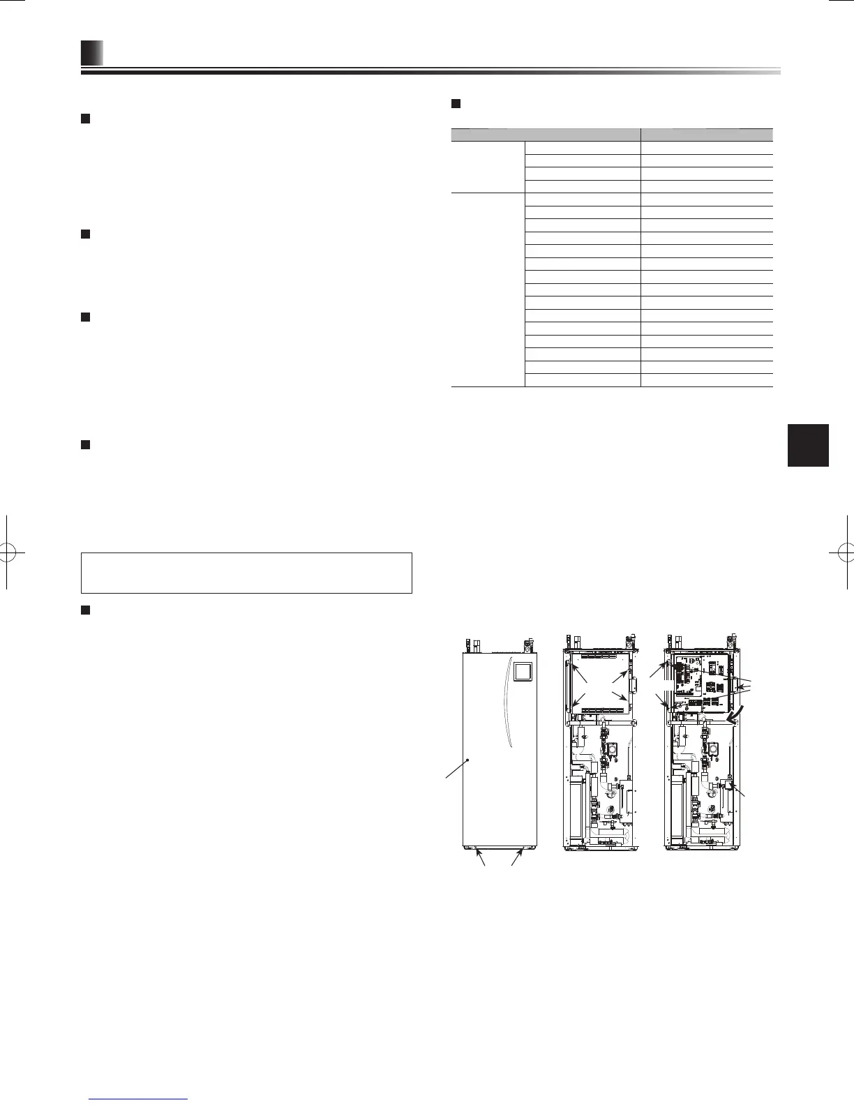
How to access Internal Components and Control and
Electrical Box
<A> Opening the front panel
1. Remove the two lower screws.
2. Slide front panel upwards to slightly and open carefully.
3.
Disconnect the relay connector connecting main controller cable and the control
board cable.
<B> Opening the control and electrical box cover
1. Remove the 4 screws.
2.
Slide the control and electrical box cover upwards slightly and remove facing
panel.
<C> Accessing the back of the control and electrical box
The control and electrical box has 3 holding screws and is hinged on the left hand side.
1. Remove the holding screw on the control and electrical box.
2. The control and electrical box can then be swung forward on the left hand
hinges.
N
ote:
1. Before accessing back of control and electrical box release cables from
the tie straps attached to the cross-support.
2.
After servicing, re-secure all cables using straps provided. Reconnect
main controller cable to its relay connector. Replace front panel and re-
secure screws at base.

 Loading...