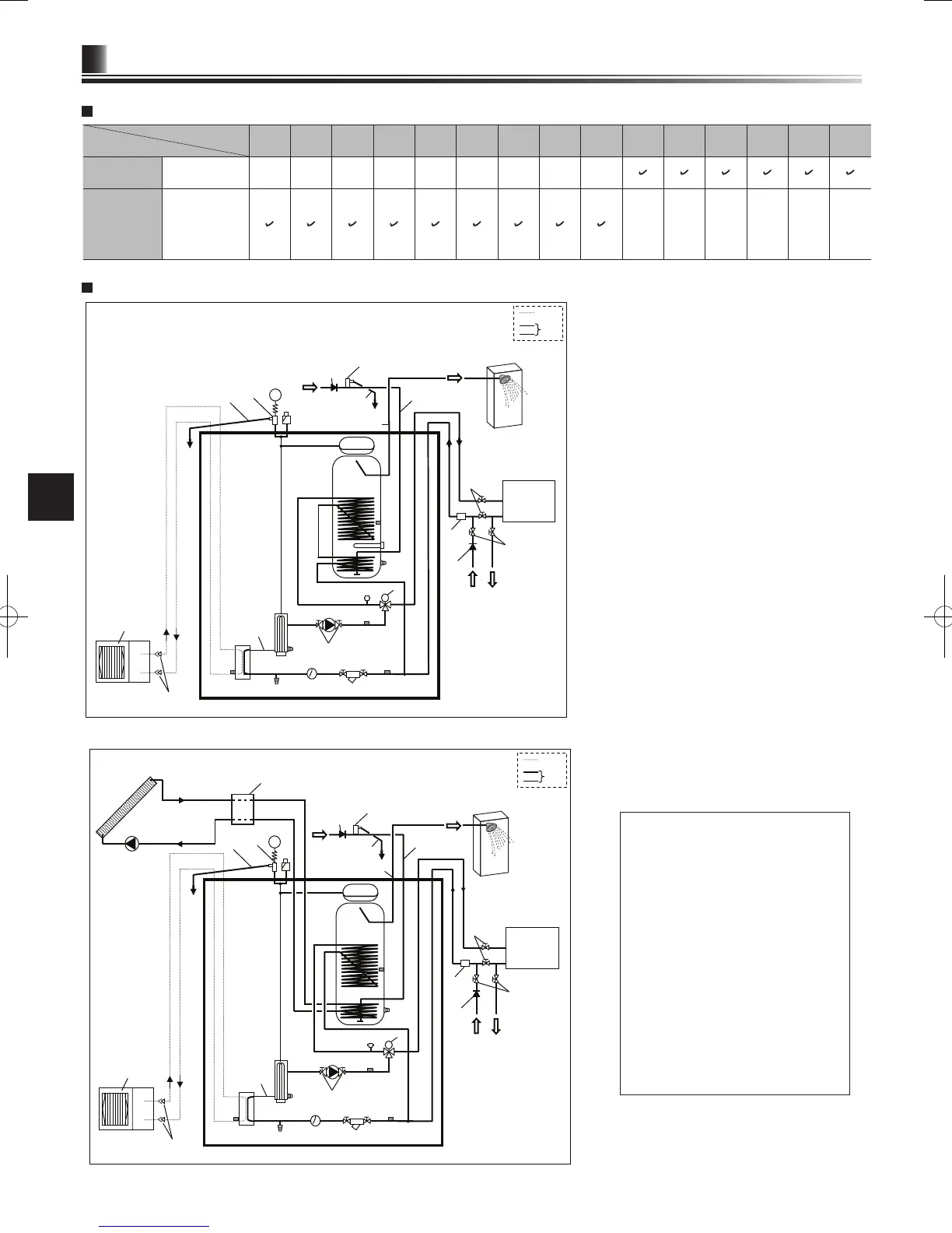
<EHST20C-*M*HB/ *M*B> (Split model system)
DHW
Local system
*1
Cylinder unit
Cold water
Drain
Drain
Flare connections
<Figure 3.5>
A. Refrigerant pipe
B. Water pipe
1. Plate heat exchanger
2. Flexible hose
3. Booster heater 1,2
4. Drain cock (booster heater)
5. Pump valve
6. Water circulation pump 1
7. 3-way valve
8. Manual air vent
9. Manometer
10. Pressure relief valve (3 bar)
11. Automatic air vent
12. Expansion vessel (except EHST20C-*M*EB)
13. DHW tank
14. Drain cock (DHW tank)
15. Flexible hose
16. Immersion heater (only for EH*T20*-*M*HB)
18. Strainer valve
19. Flow switch
20. Drain cock (primary circuit)
21. THW1
22. THW2
23. THW5
24. TH2
25. Outdoor unit
26. Drain pipe (eld supply)
27. Cold water inlet pipe
28. DHW outlet connection
29. Back ow prevention device (eld supply)
30. Isolating valve (eld supply)
31.
Magnetic lter (eld supply) (recommended)
32. Solar panel (eld supply)
33. Solar hydraulic kit (kit to be compatible for use
with FTC 4 (eld supply)
37. Pressure relief valve (10 bar) (accessory)
*1 Refer to Page 10.
Note
•
To enable draining of the cylinder unit an
isolating valve should be positioned on both
the inlet and outlet pipework. No valve
should be tted between the pressure relief
valve (item 37) and the cylinder unit (safety
matter).
•
Be sure to install a strainer, on the inlet
pipework to the cylinder unit.
•
Suitable drain pipework should be attached
to all relief valves in accordance with your
country’s regulations.
•
A backow prevention device must be
installed on the cold water supply pipework
(IEC 61770)
•
When using components made from
different metals or connecting pipes made
of different metals insulate the joints to
prevent any corrosive reaction taking place
which may damage the pipework.
Drain
Drain
Water
supply

 Loading...