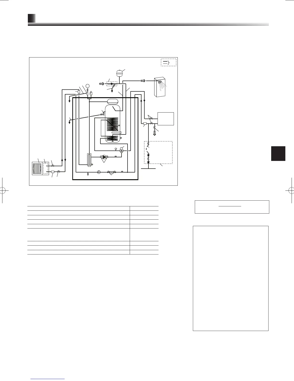
<EHPT20X-VM2HB> (UK Packaged model system)
DHW
Local system
*1
Flexible hose
(Temporary connection)
Mains water supply
Cylinder unit
Cold water
Drain
Drain
Drain
Drain
<Figure 3.7>
Model name EHPT20X-VM2HB
Maximum supply pressure to the pressure reducing valve 16 bar
Operating pressure (Potable side) 3.5 bar
Expansion vessel charge setting pressure (Potable side) 3.5 bar
Expansion valve setting pressure (Potable side) 6.0 bar
Immersion heater specication (Potable side)
* EN60335/Type 3000W single phase 230V 50Hz, length 460 mm
** Use only Mitsubishi Electric service parts as a direct replacement.
3000 W, 230 V
DHW tank capacity 200 L
Mass of the unit when full 332 kg
Maximum primary working pressure 2.5 bar
UK Packaged model system
<Example>
<Table 3.8>
Note
• To enable draining of the cylinder unit an isolat-
ing valve should be positioned on both the inlet
and outlet pipework. No valve should be tted
between the expansion valve (item 35) and the
cylinder unit (safety matter).
•
Be sure to install a strainer, on the inlet pipe-
work to the cylinder unit.
•
Suitable drain pipework should be attached to
all relief valves in accordance with your coun-
try’s regulations.
•
When using components made from different
metals or connecting pipes made of different
metals insulate the joints to prevent any corro-
sive reaction taking place which may damage
any pipework.
•
Filling loop’s exible hose must be removed fol-
lowing the lling procedure. Item provided with
unit as loose accessory.
•
Install the inlet control group (item 35) above
the level of the T&P relief valve (item 17).
This will ensure DHW tank will not require
drain-down to service/maintain the inlet control
group.
B. Water pipe
1. Plate heat exchanger
3. Booster heater 1,2
4. Drain cock for booster heater)
5. Pump valve
6. Water circulation pump 1
7. 3-way valve
8. Manual air vent
9. Manometer
10. Pressure relief valve
11. Automatic air vent
12. Expansion vessel
13. DHW tank
14. Drain cock for DHW tank
15. Flexible hose
16. Immersion heater (only for EH*T20*-*M*HB)
17. T&P relief valve
18. Strainer valve
19. Flow switch
20. Drain cock for primary circuit
21. THW1
22. THW2
23. THW5
25. Outdoor unit
26. Drain pipe (eld supply)
27. Cold water inlet pipe
28. DHW outlet connection
30. Isolating valve (eld supply)
31.
Magnetic lter (eld supply) (recommended)
34. Strainer (eld supply)
35.
Inlet control group supplied with UK model ONLY*
36.
Filling loop (Ball valves, check valves, and exible
hose) supplied with UK model ONLY*
38.
Potable expansion vessel supplied with UK model
ONLY*
*Please refer to PAC-WK01UK-E Installation Manual
for more information.
*1 Refer to Page 10.

 Loading...