3. WIRING
3-16
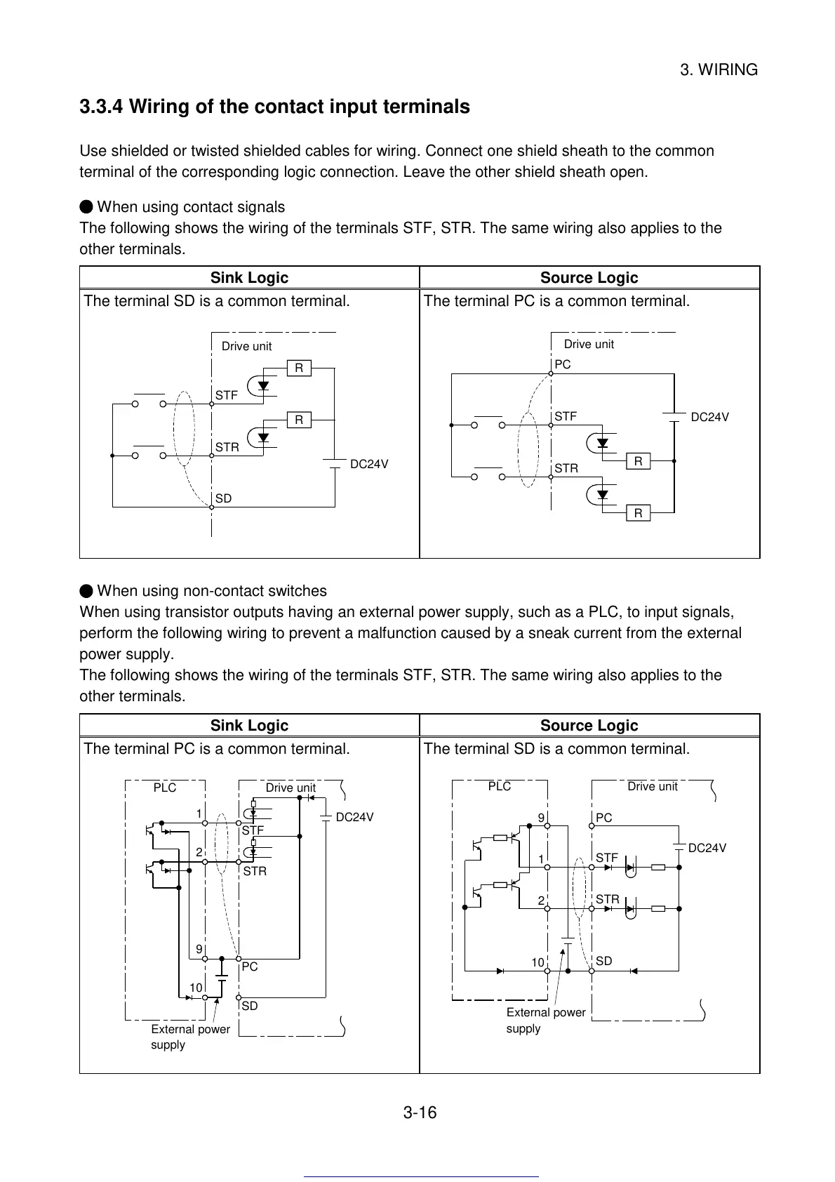
3.3.4 Wiring of the contact input terminals
Use shielded or twisted shielded cables for wiring. Connect one shield sheath to the common
terminal of the corresponding logic connection. Leave the other shield sheath open.
When using contact signals
The following shows the wiring of the terminals STF, STR. The same wiring also applies to the
other terminals.
Sink Logic Source Logic
The terminal SD is a common terminal.
R
R
STF
STR
SD
DC24V
Drive unit
The terminal PC is a common terminal.
PC
STF
STR
R
R
DC24V
Drive unit
When using non-contact switches
When using transistor outputs having an external power supply, such as a PLC, to input signals,
perform the following wiring to prevent a malfunction caused by a sneak current from the external
power supply.
The following shows the wiring of the terminals STF, STR. The same wiring also applies to the
other terminals.
Sink Logic Source Logic
The terminal PC is a common terminal.
1
2
9
10
SD
PC
STR
STF
External power
supply
PLC
Drive unit
DC24V
The terminal SD is a common terminal.
9
1
2
10
PC
STF
STR
SD
DC24V
Drive unitPLC
External power
supply
Get other manuals https://www.bkmanuals.com
 Loading...