8 PARAMETER FUNCTIONS
8-12
8.3 Selection of the Speed Command
8.3.1 Selection of the analog speed command specifications
Initial value
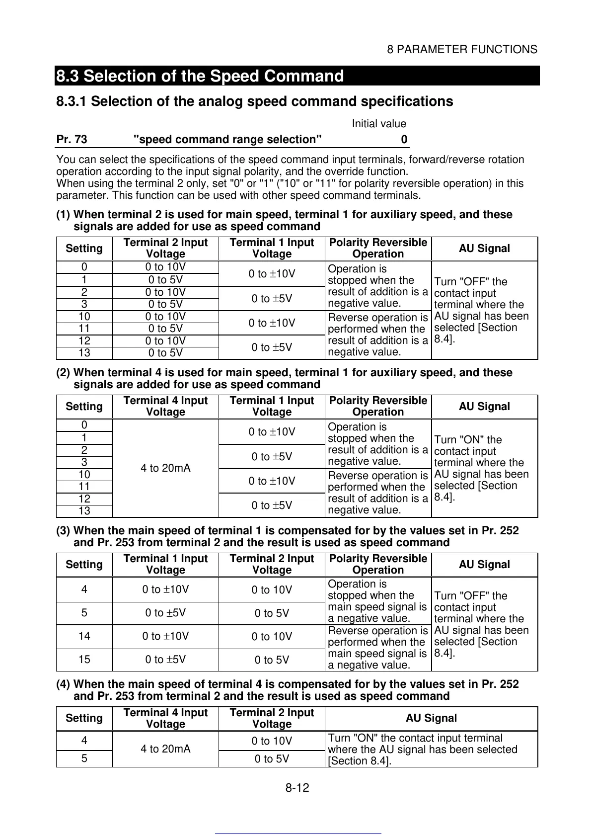
Pr. 73 "speed command range selection" 0
You can select the specifications of the speed command input terminals, forward/reverse rotation
operation according to the input signal polarity, and the override function.
When using the terminal 2 only, set "0" or "1" ("10" or "11" for polarity reversible operation) in this
parameter. This function can be used with other speed command terminals.
(1) When terminal 2 is used for main speed, terminal 1 for auxiliary speed, and these
signals are added for use as speed command
Setting
Terminal 2 Input
Voltage
Terminal 1 Input
Voltage
Polarity Reversible
Operation
AU Signal
0 0 to 10V
1 0 to 5V
0 to
±
10V
2 0 to 10V
3 0 to 5V
0 to
±
5V
Operation is
stopped when the
result of addition is a
negative value.
10 0 to 10V
11 0 to 5V
0 to
±
10V
12 0 to 10V
13 0 to 5V
0 to
±
5V
Reverse operation is
performed when the
result of addition is a
negative value.
Turn "OFF" the
contact input
terminal where the
AU signal has been
selected [Section
8.4].
(2) When terminal 4 is used for main speed, terminal 1 for auxiliary speed, and these
signals are added for use as speed command
Setting
Terminal 4 Input
Voltage
Terminal 1 Input
Voltage
Polarity Reversible
Operation
AU Signal
0
1
0 to
±
10V
2
3
0 to
±
5V
Operation is
stopped when the
result of addition is a
negative value.
10
11
0 to
±
10V
12
13
4 to 20mA
0 to
±
5V
Reverse operation is
performed when the
result of addition is a
negative value.
Turn "ON" the
contact input
terminal where the
AU signal has been
selected [Section
8.4].
(3) When the main speed of terminal 1 is compensated for by the values set in Pr. 252
and Pr. 253 from terminal 2 and the result is used as speed command
Setting
Terminal 1 Input
Voltage
Terminal 2 Input
Voltage
Polarity Reversible
Operation
AU Signal
4 0 to
±
10V
0 to 10V
5 0 to
±
5V
0 to 5V
Operation is
stopped when the
main speed signal is
a negative value.
14 0 to
±
10V
0 to 10V
15 0 to
±
5V
0 to 5V
Reverse operation is
performed when the
main speed signal is
a negative value.
Turn "OFF" the
contact input
terminal where the
AU signal has been
selected [Section
8.4].
(4) When the main speed of terminal 4 is compensated for by the values set in Pr. 252
and Pr. 253 from terminal 2 and the result is used as speed command
Setting
Terminal 4 Input
Voltage
Terminal 2 Input
Voltage
AU Signal
4
0 to 10V
5
4 to 20mA
0 to 5V
Turn "ON" the contact input terminal
where the AU signal has been selected
[Section 8.4].
Get other manuals https://www.bkmanuals.com
 Loading...