24
2 Replacement from FX3U to FX5U
2.4 Conversion of the Projects
•FX5U
■Cable sizes for European type terminal block
Suitable wiring and tightening torque are described below.
2.4 Conversion of the Projects
For the conversion method of the project, refer to Page 32 Conversion of the Projects.
2.5 Replacement of the PLC
The main points to consider during replacement of the CPU module and extension modules are explained below.
For details of each item, check the reference pages in this document, and related manuals such as the PLC Hardware Manual
and Programming Manual.
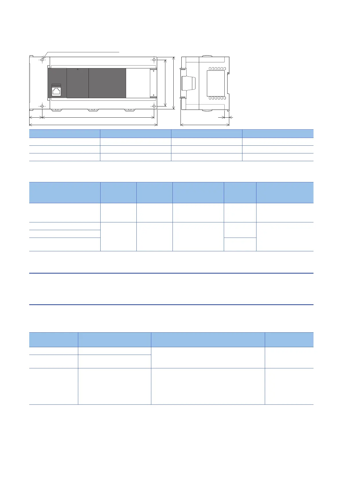
External color: Munsell 0.6B7.6/0.2
Unit: mm
The terminal block uses M3 terminal
screws
35 mm width DIN rail can be
installed
Model name W: mm W1: mm Weight: kg
FX5U-32M 150 123 0.70
FX5U-64M 220 193 1.00
FX5U-80M 285 258 1.20
Wire size for
one wire
Wire size for
two wires
Wire ferrule with
insulation sleeve
(wire size)
Tightening
torque
Stripping dimensions of
electric wire ends
Built-in RS-485 communication
terminal block
Built-in analog I/O terminal block
AWG24 to
AWG20
AWG24 AWG24 to AWG20 0.22 to 0.25
N⋅m
5 mm
FX3U-485-BD, FX3U-485ADP AWG22 to
AWG20
AWG22 AWG22 to AWG20 0.22 to 0.25
N⋅m
9 mm
FX5-485-BD, FX5-485ADP
FX5-4AD-ADP, FX5-4DA-ADP, FX5-
4AD-PT-ADP, FX5-4AD-TC-ADP
0.20 N⋅m
Device
classification
Item Operation content and points of attention Reference page
CPU module Reuse of the input/output wiring Perform rewiring for the connection part of the terminal block
type.
Page 19
Other extension
modules
Wiring to each module
Verifying operation of the
equipment
Operation and test of the PLC program Operate the converted PLC program and hardware devices,
and check and adjust the device function and operation
timing.
Be aware of the precautions described on the reference page
for replacing the project, and check that the devices operate
as they are designed.
Page 32
W1 (mounting hole pitch)22
80 (mounting hole pitch)
90
W83
8
2-4.5-diam mounting hole (32M)
4-4.5-diam mounting hole (64M, 80M)
There is no mounting hole * for 32M.
*
*

 Loading...


