3. SIGNALS AND WIRING
3 - 54
3.7.2 Base circuit shut-off delay time function
The base circuit shut-off delay time function is used to prevent vertical axis from dropping at a forced stop
(EM2 goes off) or alarm occurrence due to delay time of the electromagnetic brake. Use [Pr. PC16] to set
the delay time between completion of EM2 (Forced stop 2) or activation of MBR (Electromagnetic brake
interlock) due to an alarm occurrence, and shut-off of the base circuit.
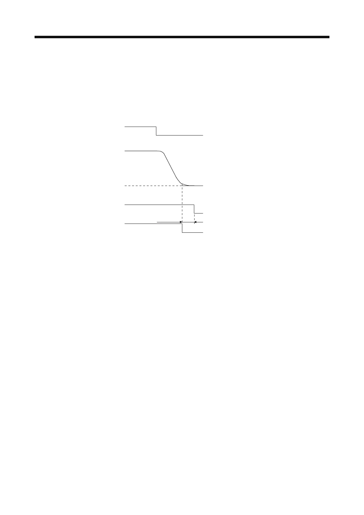
(1) Timing chart
MBR
(Electromagnetic
brake interlock)
ON
OFF (Enabled)
Base circuit
(Energy supply to
he servo motor)
0 r/min
Servo motor speed
ON
OFF (Enabled)
EM2 (Forced stop 2)
ON
OFF
[Pr. PC16]
When EM2 (Forced stop 2) turns off or an
alarm occurs during driving, the servo motor
will decelerate based on the deceleration
time constant. MBR (Electromagnetic brake
interlock) will turn off, and then after the
delay time set in [Pr. PC16], the servo
amplifier will be base circuit shut-off status.
(2) Adjustment
While the servo motor is stopped, turn off EM2 (Forced stop 2), adjust the base circuit shut-off delay
time in [Pr. PC16], and set the value to approximately 1.5 times of the smallest delay time in which the
servo motor shaft does not freefall.
 Loading...
