14. COMMUNICATION FUNCTION
14 - 34
14.5.9 Output signal pin on/off (output signal (DO) forced output)
In the test operation mode, the output signal pins can be turned on/off regardless of the servo status. Using
command [9] [0], disable the external input signals in advance.
(1) Selecting output signal (DO) forced output in the test operation mode
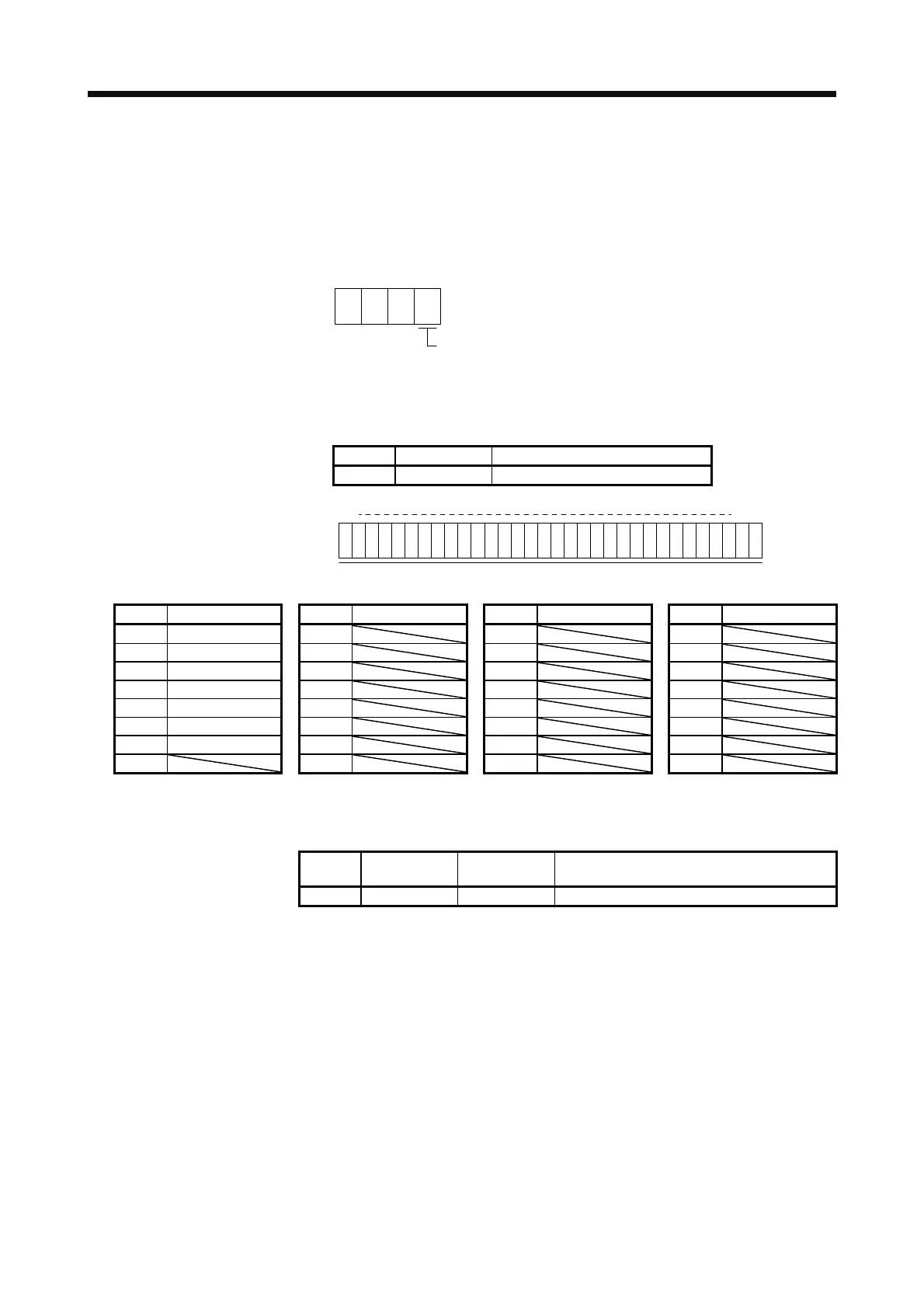
Transmit command + [8] [B] + data No. [0] [0] + data "0004" to select output signal (DO) forced output.
004
Selection of test operation mode
4: Output signal (DO) forced output
0
(2) External output signal on/off
Transmit the following communication commands.
Command Data No. Set data
[9] [2] [A] [0] See below.
b31 b1b0
1: On
0: Off
Command of each bit is transmitted to the master station as hexadecimal data.
Bit CN1 connector pin Bit CN1 connector pin Bit CN1 connector pin Bit CN1 connector pin
0 49 8 16 24
1 24 9 17 25
2 23 10 18 26
3 25 11 19 27
4 22 12 20 28
5 48 13 21 29
6 33 14 22 30
7 15 23 31
(3) Output signal (DO) forced output
Transmit command [8] [B] + data No. [0] [0] + data to stop output signal (DO) forced output.
Command Data No.
Transmission
data
Selection of test operation mode
[8] [B] [0] [0] 0000 Test operation mode cancel
 Loading...
