6 - 20 6 - 20
MELSEC-Q
6 PROGRAMMING
6.3 For Use on Remote I/O Network
System configuration used in the program explanation
(1) System configuration
tototo
Q
C
P
U
Power
supply
module
X/Y100
X/Y13F
X/Y140
X/Y17F
X/Y180
X/Y18F *1
Remote master station (Network No.1) Remote I/O station (Station No.1)
Q
J
7
2
L
P
2
5
Power
supply
module
Q
6
2
H
L
C
Q
X
4
2
Q
Y
4
2
P
Q
J
7
1
L
P
2
1
2
5
2
5
-
-
*1: Device numbers are on the basis of the remote I/O master station.
The following table shows the device numbers on the basis of the remote
station.
Module Device numbers on the basis of
master station
Device numbers on the basis of
remote station
QX42 X100 to X13F X0 to X3F
QY42P X140 to Y17F Y40 to Y7F
Q62HLC X/Y180 to X/Y18F X/Y80 to X/8F
(2) Program conditions
The programs are executed to control the temperature measured by the
thermocouple (K: -200 to 1372
) connected to channel 1.
• According to input signals, normal control/program control/manual control2
(simplified analog/digital conversion)/cascade control is executed.
• They include write data error code reading and error code resetting programs.
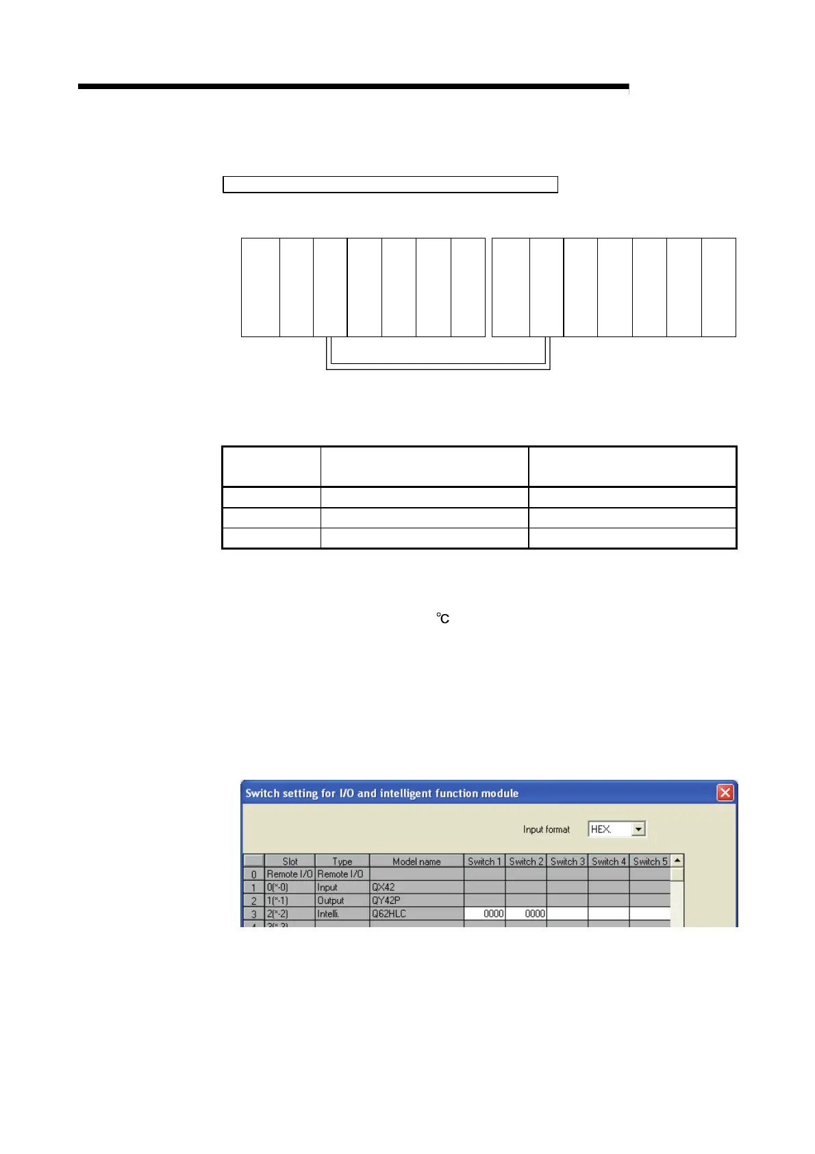
(3) Intelligent function module switch setting
Set the intelligent function module switch setting as follows.
For details of the intelligent function module switch setting, refer to Section 4.5.