10 - 1 10 - 1
MELSEC-Q
10 PART NAMES
10. PART NAMES
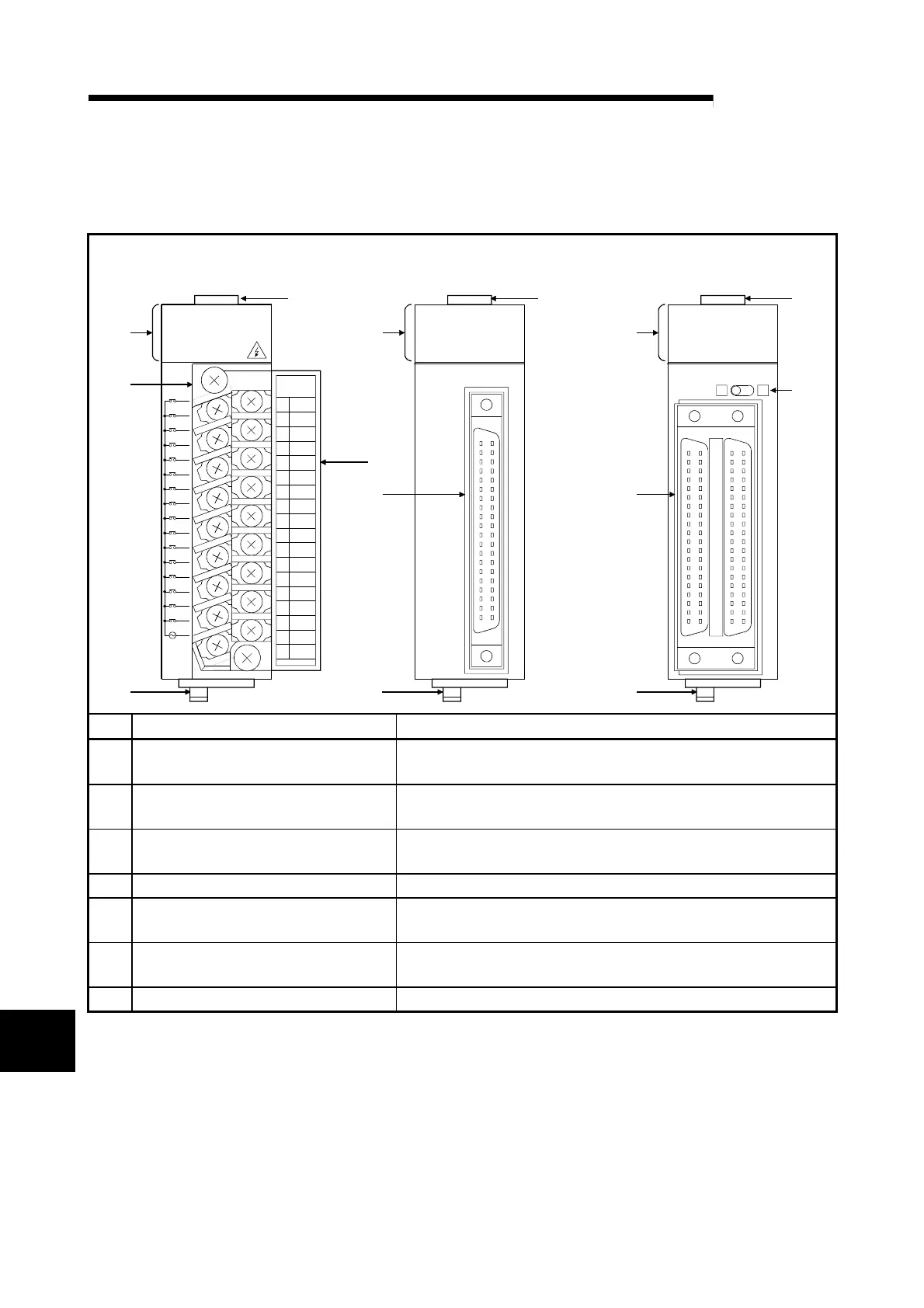
This chapter explains the part names of I/O modules.
18-point screw terminal block type (other than
high-speed input module)
40-pin connector type
0
1
2
3
4
5
6
7
8
9
A
B
C
D
E
F
COM
QX10
NC
100VAC
8mA60Hz
7mA50Hz
QX41
24VDC
4mA
QX41
QX42
24VDC
4mA
QX42
DISPLAY
F L
1
2
3
4
5
6
7
8
9
10
11
12
13
14
15
16
17
18
4)
1) 1)
2)2)
)
)
) 7)
5) 5)
6)
1)
01234567
8 9 ABCDEF
01234567
89ABCDEF
01234567
89ABCDEF
01234567
89ABCDEF
01234567
89ABCDEF
7)
No. Name Description
1) Module fixing hook
Hook used to fix the module to the base unit.
(Single-motion installation)
2) I/O indicator LED
Used to indicate the I/O status (on/off). The corresponding LED turns
on when the I/O status is on.
3) Terminal block
A 18-point terminal block for connecting a power line and I/O signal
lines
4) Terminal cover Terminal cover with recording paper
5) 40-pin connector
Designed for 32- or 64-point module and used to connect power and
I/O signal wires.
6) Indication selector switch
*1
Used to switch the LED indications between the first-half 32 points
and latter-half 32 points of a 64-point module.
7) Module loading lever Used to mount the module on the base unit.
*1: Operate the indication selector switch with your fingertip.
Do not use a screwdriver or similar tool as it may damage the switch.
10

 Loading...