11 - 4 11 - 4
MELSEC-Q
11 I/O MODULE TROUBLESHOOTING
11.2 Output Circuit Troubleshooting
This section describes possible problems with output circuits and their corrective
actions.
Table 11.2 Output Circuit Problems and Corrective Actions
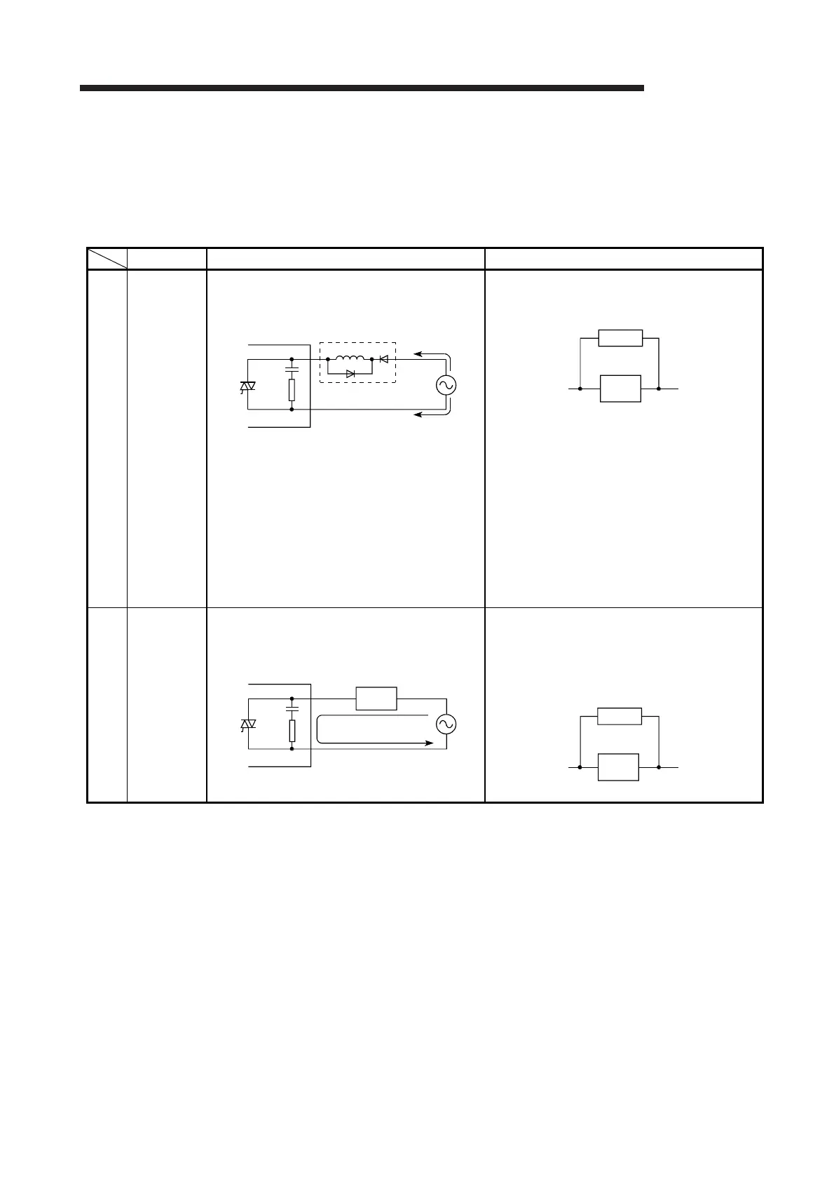
Condition Cause Corrective action
Example 1
When the
output is
off,
excessive
voltage is
applied to
the load.
• Load is half-wave rectified inside (in some
cases, this is true of a solenoid).
• When the polarity of the power supply is as
shown in [1], C is charged. When the polarity is
as shown in [2], the voltage charged in C plus
the line voltage are applied across D1. Max.
voltage is approx. 2.2E.
(If a circuit is used in this way, it does not pose
a problem to the output element. But it may
cause the diode, which is built into the load, to
deteriorate, resulting in a fire, etc.)
• Connect a resistor several tens to hundreds of
kΩ across the load.
Example 2
The load
does not
turn off.
(triac
output)
• Leakage current due to built-in surge
suppressor.
• Connect a resistor across the load.
(When the wiring distance from the output
module to the load is long, there may be a
leakage current due to the line capacity.)
(To the next page)
QY22
[1]
[2]
D1
Output module
Load
Load
Resistor
QY22
Output module
Leakage current
Load
Load
Resistor

 Loading...