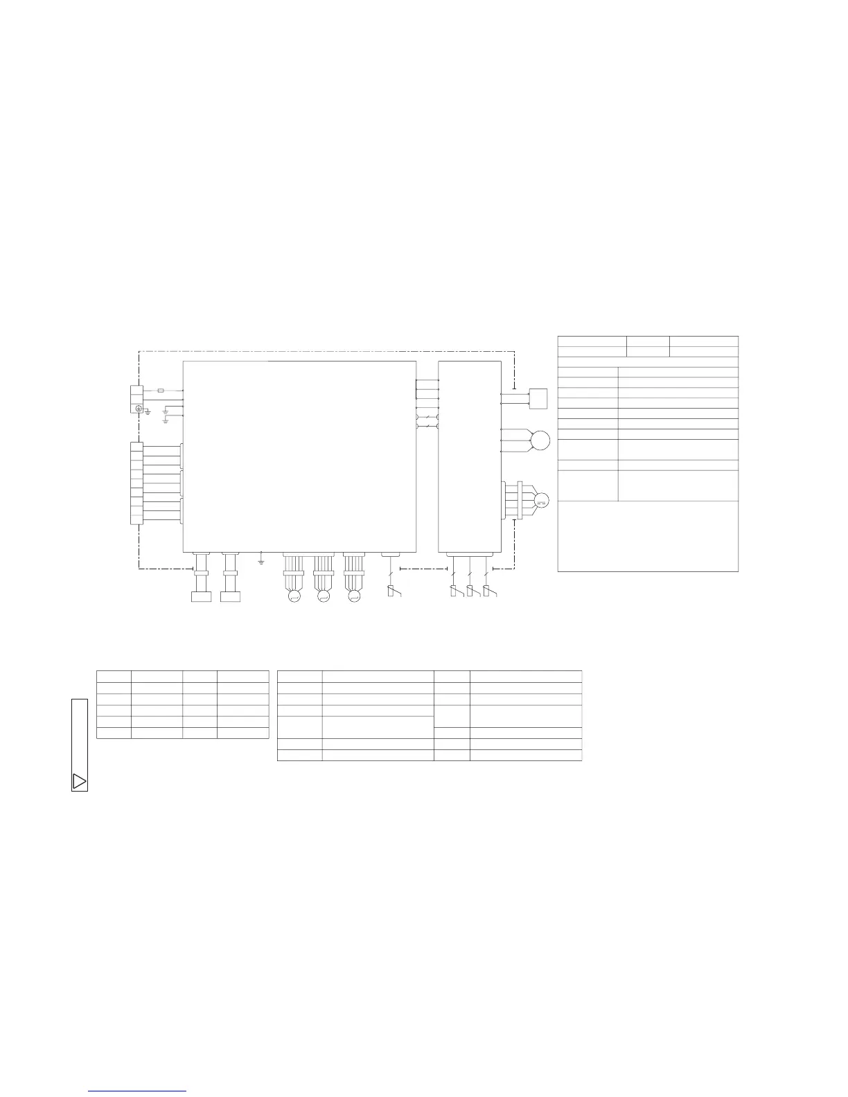
Color Marks
Mark Color Mark Color Item
Meaning of Marks
Description Item Description
BK BRBlack Brown
BL YEBlue Yellow
RD Y㧛GRed Yellow㧛Green
WH White
OR Orange
WIRING DIAGRAM
EEV
S
BK
WH
RD
V
W
U
FMo
CM
R
CNTH
CNFAN
S-2
BK
WH
WH
S-1
CNSUB
CNMAIN
S
R
BK
WH
IN
IN
S
R
O
O
250V 15A㧛
FUSE
CN20S
G2
Y㧛G
C-2
RD
C-1
CN20V
CN20V
5
2
G1
Y㧛G
G
Y㧛G
CNEEV1
CNEEV3
CNTH
TB2
CNA
CNB
CNC
TB1
N
L
A
EEV
B
EEV
C
Y㧛G
WH
BK
UNIT A
UNIT B
UNIT C
M
3㨪
M
M
M
M
POWER
SUPPLY
WH
RD BL
PWB 2㧔SUB㧕
PWB 1㧔MAIN㧕
20S
HEATER
WH
RD
CNHEAT
T2
T1
R
OR
YE
250V 20A
3
2
1
BK
WH
RD
3
2
1
3
2
1
BK
WH
BR
BK
WH
BL
2 2 2
tࠑ
tࠑ
tࠑ
tࠑ
2
Tho-S
Tho-R Tho-A Tho-D
CNA-CN20S
EEV A,EEV B
EEV C
R
Compressor motor
Electric expansion valve
㧔coil㧕
Reactor
Tho-A
Tho-D
Heat exchanger sensor
Outdoor air temp. sensor
Discharge pipe temp. sensor
CM
Tho-R
Connector
20S 4 Way valve㧔coil㧕
Suction pipe temp. sensor
Tho-S
FMo Fan motor
Terminal blockTB1,TB2
㧔outdoor unit㧕
HEATER Crank case heater
FunctionColorIndication lamp
Warning lampRedLed e 㧔1㧕
Self diagnosis function by led e
1 Time flash Current cut
2 Time flash Trouble of outdoor unit
3 Time flash Over current
4 Time flash Transmission error
5 Time flash Over heat of compressor
6 Time flash Error of signal transmission
7 Time flash Lock of compressor
8 Time flash Sensor error
㧔Except discharge pipe sensor㧕
Four sec light
and Discharge pipe sensor error
four sec off
Caution When the compressor does not run Immediately after
hitting on the button,wait for 5 to 10 minutes.㧔There is
possibility of delayed start.㧕
High voltage is produced in the control box. don't touch
electrical parts in the control box for 5 minutes after
cutting power supply.
Light on Outdoor fan motor error
 Loading...