'18 • SRK-SM-259
-
31
-
'09•SRK-DB-087D
Trouble of outdoor unit
Insufficient refregerant amount, Faulty power transistor, Broken compressor wire
Service valve close, Defective EEV, Defective outdoor unit PCB
.
◆
(1)
(1)
(2)
(3)
Notes (1)
(2)
(3)
36.
33.
Check coil wire resistance, see page 28.
Outdoor fan motor error
Defective fan motor, connector poor
connection, defective outdoor unit PCB
See page 35 for the fan motor and outdoor unit PCB check
After making sure the fan motor and outdoor unit PCB are
Power source reset
Is it normalized?
Malfunction by temporary noise
Replace fan motor. (If the
error persists after replacing
the fan motor, replace the
outdoor unit PCB.)
the fan motor and outdoor
unit
ourdoor unit PCB
outdoor unit
Replace outdoor fan motor
AC
AC
AC
AC
source
source
AC
AC
wire
source
source
unit
unit
unit
-
-
-
operation
pro
nor
'09•SRK-DB-087D
Outdoor fan motor error
Rotor lock
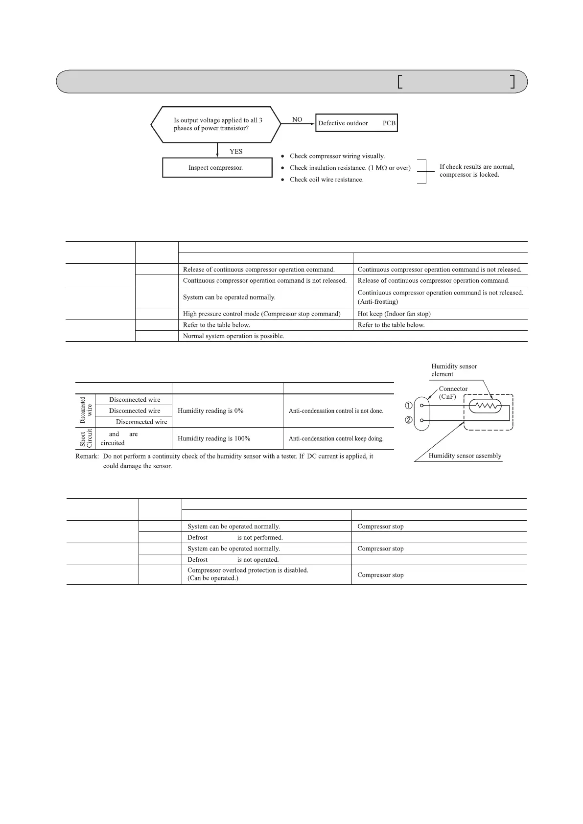
(8) Phenomenon observed after short-circuit, wire breakage on sensor
(a) Indoor unit
Defective fan motor, connector poor
connection, defective outdoor PCB
Defective compressor, defective
outdoor unit PCB
Sensor
Operation
mode
Phenomenon
Short-circuit Disconnected wire
Room temperature
sensor
Cooling
Heating
Heat exchanger
sensor
Cooling
Heating
Humidity sensor
Cooling
Heating
■
Humidity sensor operation
Failure mode Control input circuit reading
Air conditioning system operation
①
②
①②
①
-
short-
.
②
See page 28.
unit
'09•SRK-DB-087D
Outdoor fan motor error
Rotor lock
(8) Phenomenon observed after short-circuit, wire breakage on sensor
(a) Indoor unit
Defective fan motor, connector poor
connection, defective outdoor PCB
Defective compressor, defective
outdoor unit PCB
Sensor
Operation
mode
Phenomenon
Short-circuit Disconnected wire
Room temperature
sensor
Cooling
Heating
Heat exchanger
sensor
Cooling
Heating
Humidity sensor
Cooling
Heating
■
Humidity sensor operation
Failure mode Control input circuit reading
Air conditioning system operation
①
②
①②
①
-
short-
.
②
(9) Checking the indoor electrical equipment
(a) Indoor unit PCB check procedure
(b) Outdoor unit
Is there voltage between terminal
blocks
①
and
②
? (AC 220/230/240
V)
Indoor electrical components
are normal.
Is the voltage between terminal
blocks
②
and
③
oscillating between
DC 0 and 20V?
Inspect power source
operation
operation
for outdoor unit.
Replace fuse.
Replace indoor unit
PCB.
Is the fuse burnt out? (3.15 A)
YES
YES
YES
NO
NO
NO
(b) Indoor unit fan motor check procedure
1) Indoor unit PCB output check
2) Fan motor resistance check
Sensor
Operation
mode
Phenomenon
Shortcircuit Disconnected wire
Heat exchanger
sensor
Cooling
Heating
Ourdoor air
temperature sensor
Cooling
Heating
Discharge pipe
sensor
All modes
Measuring point Resistance when normal
①
−
③
−
④
−
③
−
Defrost operation is performed for 10 minutes at approx. 35 (model SRC35:45) minutes.
Defrost operation is performed for 10 minutes at approx. 35 (model SRC35:45) minutes.
k
⑥⑤④③②①
⑥⑤④③②①
FM
i
DC15V
Indoor unit PCB
DC 308-336V
DC several V
(4-6 V)
CNU
(–)
GND
Blue
Yellow
White
Black
Red
Measuring
point
Voltage range when
normal
①
−
③
④
−
③
⑤
−
③
-
-
unit
① ④ ⑤
unit
unit
 Loading...