'18 • SRK-SM-259
-
34
-
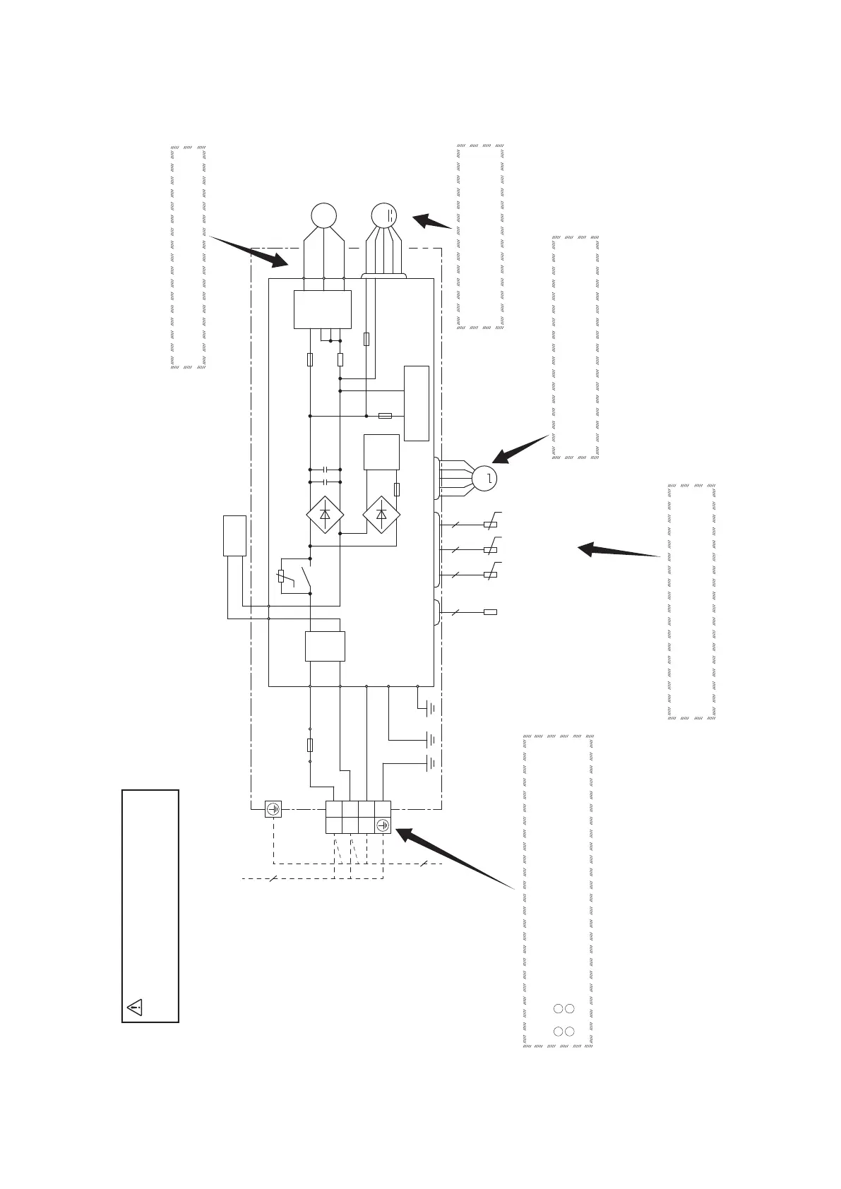
SWITCHING POWER
CIRCUIT
F1
250V 2A
NW
F3 T 1A L 250V
NU
NV
P
250V 20A
F2
V
V
TRANSISTOR
POWER
(WHITE)
U
(RED)
W
(BLACK)
U
W
M
3~
COMPRESSOR
MOTOR
M
FAN MOTOR
++
F4
250V 10A
CIRCUIT
PAM
PCB ASSY
T1 T2
FILTER
NOISE
R.IN
S.IN
C-2
G1
(BLACK)
(WHITE)
(RED)
GREEN)
(YELLOW/
T 250V E 15A
F7
1
2
3
L
N
M
CN20S CNTH CNEEV
CNFAN
HEAT EXCH. SENSOR
(OUTDOOR UNIT)
OUTDOOR AIR
TEMP.SENSOR
DISCHARGE PIPE
TEMP. SENSOR
SOLENOID COIL FOR
4-WAY VALVE
ELECTRIC EXPANSION
VALVE(COIL)
REACTOR
(YELLOW)
(ORANGE)
BLOCK
TERMINAL
TB1
G2
GREEN)
(YELLOW/
GREEN)
(YELLOW/
t°
t°
t°
t°
4
2 2 2 2
3
Power source
1 Phase
220-240V 50Hz
◆ Check point of outdoor unit
CAUTION
-
HIGH VOLTAGE
High voltage is produced in the control box. Don't touch
electrical parts in the control box for 5 minutes after the
unit is stopped.
◆Power source and serial signal inspection
1
to
2
:
2 to
3 : Normal if the voltage oscillates between DC 0 and approx. 20V
◆Inspection of resistance value of sensor
Remove the connector and check the resistance value.
See the section of sensor characteristics on page 27.
◆Inspection power transistor
Remove the fasten terminal and test output voltage.
◆Inspection of electronic expansion valve
See page 36.
◆Inspection of outdoor fan motor
See page 36.
(11) Outdoor unit inspection points
Models SRC25ZSP-W, 35ZSP-W

 Loading...