A920: WCDMA PA
Description
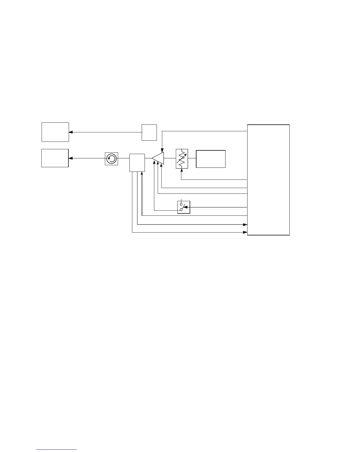
The U410 provides necessary attenuation of the TX carrier before reaching the PA so that it doesn‘t exceed the maximum allowable input of 1dBm of the PA and to con-
trol the overall power output of the transceiver. U410 has a 16-18 dB of attenuation depending on the control voltage VGC2 applied at HYBOUT1 and HYBOUT2,
which is controlled by Harmony Lite.
U420 is a three-stage power amplifier handling the band of WCDMA Tx frequencies between 1920 - 1980MHz. The nominal expected maximum gain is ~30dB.
HARMONY_LITE controls the RF biasing of the amplifier at pins #4 (PA_BIAS1) and #5 (PA_BIAS2) with a control range of 0 - 2.5v. HARMONY_LITE also con-
trols pin #12 (VLD) for PA load switching. Although not implemented, the theory of PA load switching in WCDMA is vitally important to conserve battery life and to
avoid unnecessary radio interference with base stations. When VLD is at a low state (0v), the transmitter is in high power mode, consuming higher current but with over-
all better PA performance. When VLD is at a high state, the transmitter is in low power mode, consuming less current with overall poor PA performance. In theory, as
the Tx power level increases or decreases beyond a certain power threshold, VLD is enabled or disabled. As Tx power decreases (as requested from a base station) down
to ~14.5dBm, VLD will switch high. If Tx power is requested to increase beyond ~19dBm, VLD is switched low.
The power detector receives the amplified WCDMA RF signal at RF_IN (pin #6) from the PA. U450 is a combination directional coupler and temperature compensated
power detector with a differential output. The power detector couples the TX power input and feedbacks an output RF_DETECT to HARMONY LITE. The
TEMP_COMP also obtains the coupled power but removes the RF signal content, leaving a DC level. The DC level is feedback to HARMONY LITE. Expected nominal
loss is <. 3dB.
The isolator (FL460) provides isolation between Front-End Module (FEM) and transmitter path. Nominal insertion loss is ~ 0. 55dB.
Motorola Confidential Proprietary
4-30
Variable
Attenuator
U410
PA
U420
Temp
Sens
U440
Isolator
FL460
VGC2
PA BIAS1
VLOAD_SW
RF_ DETECT
PA BIAS2
V_DETECTOR
VRF_TX_2.775V
VLD
TEMP_COMP
TEMP_SENSE
PCAP
U3000
RF TOP
PA_ENABLE
Q401
Harmony Lite
U101
Coupler
/ RF
Detector
U450
MAX2363
U200
WCDMA_TX
 Loading...